dcmoore2
-
Posts
14 -
Joined
-
Last visited
Recent Profile Visitors
802 profile views


-
 I want to replace the fuel tank sending unit and the fuel pump and possibly the charcoal canister. My 71 originally had the return line from the pump to the tank and the charcoal canister which has since been discarded. The fuel pump on it now just has one inlet and one outlet. The return hose is still there but nothing hooked to it. The charcoal canister thing is gone, but there are lines running to the area where it was. The fuel tank has the many vent lines going all over the place and i assume it has the original sending unit with 2 lines coming out. My question is - is there an advantage to having the return line and the charcoal canister? Should i replace the fuel pump with the one with a return line and should i replace the sending unit with one with 2 lines? And should I purchase a new charcoal canister and whatever that consists of. Or, can i just do away with the return line and get the sending unit with just one line and a new fuel pump with just one line and leave the charcoal canister missing?
 -
OK - so i have replaced the blower switch. It along with the wires were burned and definitely contributed to my issues. Now I have all fan speeds EXCEPT high. Mine is different than what i see in the diagram because i had two relays on the firewall and an orange wire went into each of them. Unlike that diagram that shows both orange wires going to the same relay. I'm not sure if that had been hacked by previous owner but that is how i got it. But i think the anti dieseling crap is confusing me now........ I'll check to see if i have both orange wires or at least the hot one that comes from the horn relay connected into the relay on the firewall, which is new but it may be wired differently....and it is starting to make sense now. I will wire it the way the diagram shows, which actually just ties both orange wires together. If I dont hook up the anti dieseling orange wire into that relay, will that somehow keep something else from working downstream?
-
should the small orange fused wire be hot all the time? the blower motor works great when jumped. i spliced in a new plug and installed a new relay. i now have some fan movement on the 2nd and 3rd click of the blower switch. nothing on low and nothing on high. my next plan is to replace the blower switch inside.
-
dcmoore2 changed their profile photo
-
i adjusted almost all the way in this time. I now have cool drums but the brakes really need a lot of pressure to stop. I will now adjust out a little at a time until i feel that they are working properly, but with no heat from drag. i still think it could be the proportioning valve being gunked up or rusty inside.
-
After driving a few miles, under normal conditions, i can get out and feel the rear drums and they are very hot to the touch. They were both doing it at first so i re-adjusted the shoes, thinking that i had adjusted too tight. Now the drivers side is the only one that gets really hot. I recently replaced the master cylinder, rear wheel cylinders and all the brake lines. I have loosened the parking brake cable also - thinking that may be the culprit but it was not. I have read that the master cylinder could have been a little different than what was on it and the rod could be too long - making the brakes drag? I also have read that the proportioning valve could also be plugged or is getting too hot from the header tube being about 1/2 inch away...i am going to try and adjust the brake pedal rod to make sure clearance is there. Then i'll tackle the proportioning valve with a heat shield or wrapping the header or moving it altogether. Anyone have this same issue?
-
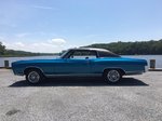
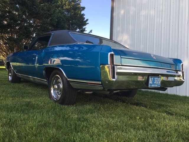
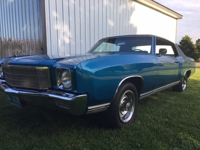
thanks - nice car too....i finally got mine done after almost 3 years...
-
you asked if the 4 wires are in the resistor? Those are the G, LB, Y & DB - correct? if so, then yes, those are still wired properly to the resistor. excuse my ignorance between relay and resistor. i appear to have a different set up for the relay. The above diagram shows both orange wires going to that relay, mine has the smaller orange wire going to a separate smaller relay. My big relay just has the large fused orange, PPL & DB on the one side then black to the other side. I will be bypassing the anti dieseling stuff also. Thanks again for the help.
-
Thanks - I have ordered a new blower motor relay along with the 3 prong plug. I will replace the blower motor relay and its wiring and the inline fuse to see where that gets me. I guess going to the Resistor next? Is there a diagram somewhere that would tell me what color wire to check, at what location, for when the blower switch is in each of its 4 speeds, to try and narrow down whether its a bad relay, switch, resistor or thermal switch ? The blower motor is new. Would that smaller orange wire, from the anti dieseling relay, being disconnected have anything to do with the blower motor not working? I would also like to eliminate the anti-dieseling. I assume since I now have electronic ignition, I wouldn't need to worry about dieseling - correct?
-
i've been slowly fixing things on this car for a while now and i am starting to tackle some wiring issues. My blower motor does not work. I have found the two orange wires coming from the firewall. The larger one with the inline fuse goes to a 4 pin resistor along with 2 other wires on the 3 prong side and then a black ground on the one pin side. The thinner orange wire shows on the wiring diagram that it should go to the same resistor and pin as the larger orange wire. But, mine was definitely not wired to that 4 pin resistor, it was wired to a separate 2 pin resistor which just has one pin on each side. But i cant find what other wire would go to the other side of the smaller 2 pin resistor. I have another free wire that comes out of the firewall, but i cant really tell what color it is. The wiring itself definitely has been HOT and i will be rewiring and installing new resistors once i figure out what goes where. thanks for any help

-
hello - i am in need of the bracket part numbers on the side of the bucket seat that holds the plastic side cover on. This bracket attaches through the hinge bolt holes and also has 2 spots to hook the seat cover to. Thanks
-
Hey Steve, The 70 fenders are slightly different than 71 & 72. They will fit but with minor modifications. Doug
-
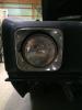
Thanks for the info. I understand the difference and reasoning behind the step in the mounting bracket. I also know that if I leave it the way it is, the bracket of the 70 fender sits on the highest section/hump of the rad support, and the headlight doesn't align properly. So, in my mind, the fender needs to be lowered by removing the front section of the fender mounting bracket, so the bracket sits down on the rad support. Would this place the fender in the proper location with the surrounding features? This appears to be about the same distance that the headlight is out of alignment with the bezel. Also, notice the bracket of the headlight extension has a gap under it. I have already modified the extensions to fit, but that doesn't change the alignment with the headlight. I will probably remove the bracket from the old 71 fender and re weld in place, but I want to make sure i have the fender aligned properly first.
-
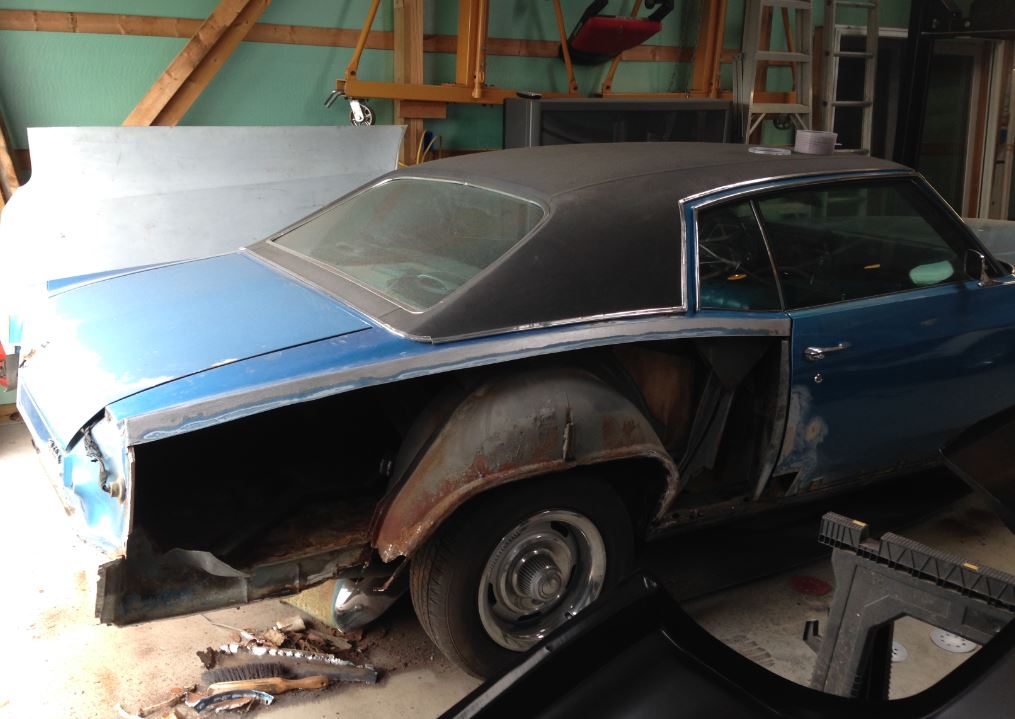
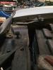
I attached 2 photos with quarters removed, so you can see what may be in the way of getting to your dent. Hope this helps.
-
I am in the process of using 70 fenders on my 71. I have noticed the difference in the mounting location to the rad support. My plan is to remove the front section/hole of the brace so the rear section of that flange will sit on the rad support. I believe this will take care of my headlight alignment issue inside the bezel. is this the proper path forward, or will this make the front of the fender sit too low?