MGD72Monte
-
Posts
500 -
Joined
-
Last visited
Other groups

MGD72Monte's Achievements
")


-
That car was part of the "Great 8" finalists for the Ridler award, along with others including, interestly enough a 70 Monte. Here is a Hagerty link to a nice write up about each of these cars as well as some pretty good pics. https://www.hagerty.com/media/events/2025-detroit-autorama-ridler-award-great-8-finalists/
-
Fuel Sending Unit Troubleshooting and Repair
MGD72Monte replied to MGD72Monte's topic in Electrical Tech
There was no problem with the wire so I did not show it in the last pics. Just in case my post was confusing; the push clip I replaced is inside the fuel tank. The pin goes through from the top side of the sending unit to the inside of the tank. Inside the tank, the push clip secures the pin to a rigid metal strap that connects to the resistor. The sending unit wire is on the outside of the tank, and it is connected to the other end of the pin. I have now re-installed the tank so I can't take another picture but I've edited some of my previous pictures to try to clarify the difference between where the push clip goes (underside of pin) and where the sending wire would go (top side of pin). Hopefully this clarifies the difference. Sorry for any confusion. Below is a side view of the sending unit showing where the sending wire goes on the top side and where the push clip goes on the other side. Below is view of the portion of the sending unit that is inside the tank and you can see the underside of the pin and the old push clip securing the strap. Note that the sending unit is laying on its side in this pic.

-
Fuel Sending Unit Troubleshooting and Repair
MGD72Monte replied to MGD72Monte's topic in Electrical Tech
As I've made a small change to my way forward on this repair, I thought I would explain and provide additional information which might be useful. As per my first post on this thread, in order to address the continuity problem I was having with the sending unit, I had to disconnect and clean the pin that goes through the top of the sending unit from the metal strap that goes to the sending unit resistor. In order to do this, I had to cut the small push clip holding the strap to the pin. I found a push clip that would fit from my spare junk clip pile, but as I was installing the sending unit in the tank I found the pin to be getting loose and the clip no longer secured in place. One of the reasons I had used a recycled clip (other than convenience) was that I thought it might be very difficult to find a proper replacement. However, I was pleasantly surprised when, after a bit of research on line, I found Dorman Push Nut Assortment (part no. 13441) which includes 10 push clips of different sizes, two with a 1/8" ID, which I thought should fit. After picking the set up at a local parts supplier, I found that this size clip was essentially the same as the one I removed. Once installed, it held on securely and this remained throughout the sending unit and tank re-installation. This is the new clip next to the one I cut off This is the clip I had hoped would work next to the new one Below is the new clip installed And finally, the sending unit back in the tank.


-
Fuel Sending Unit Troubleshooting and Repair
MGD72Monte replied to MGD72Monte's topic in Electrical Tech
So I will start by re-stating that I have a 1972 with a SB350. I would imagine that other than for the evap lines, the configuration should be like the other two years but I have not checked on line for part number or photo comparisons. To answer the questions, on my car the hole for the sending unit is towards the front of the tank and to the pax side of the centerline. The way the sending unit sits has the pick up line and strainer going towards the back of the car, angled slightly towards the driver's side so basically set up to be near the middle of the tank and lined up with the filler neck. The strainer essentially sits on the bottom of the tank. The float also goes towards the rear of the car, but is angled slightly in the opposite direction towards the pax side so it sits a little to the pax side of the sending unit hole therefore on the pax side of the tank and not lined up with the filler neck. I would be surprised that your float would be stuck below the fuel level, the pivot is very easy to move and it would really have to be jammed to be able to stay below the fuel level. I took the photos below of the sending unit near the sending unit hole and lined up as it would be when installed. If you want a side view of the sending unit, see my first post on this thread. Hope this helps.


-
Fuel Sending Unit Troubleshooting and Repair
MGD72Monte replied to MGD72Monte's topic in Electrical Tech
Here is some data that may be of interest. This was taken from my sending unit which I consider to be reading accurately based on the gauge indication. This data was gathered with the sending unit out of the tank but connected to the car's gauge wiring. The float was moved manually through its range of motion from the bottom stop to the top and the corresponding position of the gauge was noted as described below. Note that the resistance reading is with the tan wire coming from the gauge disconnected from the sending unit. 1. Float Position at bottom of travel - gauge reading exactly E - Multimeter reading 3.5 Ohm 2. Float Position slightly above bottom of travel - gauge reading exactly 1/4 - Multimeter reading 23 Ohm 3. Float Position slightly below half of travel - gauge reading exactly 1/2 - Multimeter reading 43 Ohm 4. Float Position at middle of travel (horizontal) - gauge reading roughly 3/4 - Multimeter reading 60 Ohm 5. Float Position at top of travel - gauge reading roughly two notches over full - Multimeter reading 107 Ohm 6. Disconnecting the Ground wire - gauge reading goes horizontal (needle at the 3 o'clock) - Multimeter reading infinity Comment: My understanding is that with the needle on E, the resistance reading should be 0 Ohms and with the needle on full it should read around 90 Ohms. It is worthy of noting that even though the float has travelled half of its range, the gauge has only moved to the 3/4 tank position. The needle now needs to travel 3/4 of the gauge range while the float only has half of its travel left.


-
Fuel Sending Unit Troubleshooting and Repair
MGD72Monte replied to MGD72Monte's topic in Electrical Tech
I agree with your concerns about simply relying on a continuity bench check to consider the unit as good that is why as per my point # “5. I took the sending unit back over to the car, connected the tan plug to the pin and grounded the sending unit and the gauge now works. I moved the float through its full range and it op checked good.” Power was flowing through the unit during this test and at the top and bottom of the float travel, the gauge reading was visibly accurate on the dash, identical to how it had been since I’ve owned the car prior to the fault showing up. This is the reason behind my calling this good. Yes, a replacement is cheaper than a partial tank of gas and yes, my unit is probably 50+ years old so way past its prime but I have found the most challenging part of restoration and maintenance to be finding good quality parts. So, I prefer repairing when I can. Unlike an in tank fuel pump, the failure consequences for a sending unit are fairly benign. In this case, based on this philosophy and the reasons I stated in my initial, I’m giving this repair a chance. Having said that, your Doorman recommendation is much appreciated. The filter and float designs appear much closer to the stock unit so if I do have an issue, I will definitely go with the Doorman 692-243 vice the Spectra. Thanks! -
Fuel Sending Unit Troubleshooting and Repair
MGD72Monte replied to MGD72Monte's topic in Electrical Tech
Joe: In my case i.e. for a 1972, the Spectra Part Number is FG91C (one outlet vice the FG91D's two). Having said that, the filter set up is the same so I appreciate your experience / insight about potential problems with that filter. This further reinforces my preference to stick with my repaired unit than to buy a new one. I'll consider having a closer look at corrosion at the other end of the strap and the resistor. Although since I found the smoking gun, and it's checking good, I'm willing to chance putting this unit back in. Rob: Your problem does seem different. My daily driver (1984 Buick) has had a similar problem than the one you are describing for several years. I ran out of gas once with the needle somewhere around 1/4 so now I refuel when it gets to 1/2. I have yet to investigate the issue because it still sort of works but it sounds like you're right, there is too much resistance somewhere in that circuit. If I was a betting man I would think it is the rheostat. I am curious to see what you find when you pull it out and especially if this is something that can be fixed as it might motivate me to pull the tank on my daily driver. Bruce: Having the gas gauge fluctuate when the tank is not full and motion is causing the fuel to slosh around is not unusual in my experience, as long as it returns to a stable point once your motion stabilises. Unless I misunderstand your post, I would think your system is OK but glad you found my write up of potential future use. -
Hey Rob, rather coincidentally I just finished a repair on a sending unit, not sure if this would help but I started a thread, link is below. Cheers
-
Not sure how common this specific issue is so I thought this was worth posting as the symptom pointed to a grounding problem but turned out to be an internal continuity issue. Hopefully someone finds this useful. Approx last Oct I was driving and noticed the gas gauge was showing over 150% full (needle at the 3 o'clock) position. I had a similar issue about 25 years ago but it went away on its own. This time it seemed to not want to budge after several fairly long drives so I added the troubleshooting to my list of winter projects. Finally got to it. 1. At first I suspected a bad ground, which given the rust of the gas tank brackets, was a reasonable assumption. So I disconnected the ground, then used a set of long jumper cables to connect the ground wire directly to the negative battery terminal. No change. 2. To confirm the gauge side of the circuit, I disconnected the connector located in the trunk (tan wire coming from the instrument cluster going to the sending unit). I grounded the wire to the trunk with an alligator clip and with ignition "on" the gauge went to Empty. This confirmed that the gauge and wire coming from it were good meaning the problem was somewhere downstream of the trunk connector. The tan wire looked fine as it disappeared between the top of the tank and the trunk floor on its way to the fuel sending unit. 3. I siphoned the gas, put the rear of the car on ramps and dropped the tank onto a creeper covered with some cardboard. No visible issues noted by looking at the top of the sending unit except years of dirt and some rust. I reconnected the tan wire to the plug in the trunk and grounded the sending unit ground wire. With ignition "on" initially there was nothing but as I played around trying to ground the sending unit casing, the gauge went to empty (as it should given the fuel tank was now empty) but further fiddling would see it go back to 3 o'clock again. Eventually by checking for continuity through the sending unit i.e. between the ground wire and the pin onto which the tan wire is plugged in, I found that continuity would go on and off as I pushed the pin back and forth. 4. At this point I knew I had to remove the sending unit. I was not keen on doing this given the amount of grime on top of the tank around that area. I cleaned the area as best as I could and carefully removed the lock ring and pulled the sending unit out. After some bench checking I found that continuity was good, except through the pin. The pin goes through the top of the sending unit via a plastic and rubber grommet and is secured in place on the underside of the sending unit top with a round push clip. The clip secures the pin to a metal strap that connects to the sending unit resistor (see pic below) and continuity appeared to be lost under the push clip between the metal strap and the pin. I could see a bit of corrosion at the push clip and the pin showed what could be corrosion as well. I tried to remove the push clip but found this impossible so I cut it with the tip of a set of tin snips. I cleaned the pin using my bench wire wheel, and found a push clip that would fit from my spare junk clip pile, and reassembled. I tested for continuity and found it to be good. The pic below shows the cleaned pin, the plastic part of the grommet and my "new" push clip. You can see the metal strap (vertical piece covered by a black plastic coating). The pic below shows the underside of the top of the sending unit with the pin installed and secured with the strap by my "new" push clip. The rubber grommet looks a little rough but was still soft and a replacement would be difficult to source. I will probably add a dab of silicone on the top side of the unit around the pin. Below is a view of the reinstalled pin from the top 5. I took the sending unit back over to the car, connected the tan plug to the pin and grounded the sending unit and the gauge now works. I moved the float through its full range and it op checked good. Below is the complete unit ready for installation. 6. I thought about buying a new sending unit, specifically the SPECTRA PREMIUM FG91C, however, I will reinstall my old one for the following reasons: a. I am familiar with the indication of my unit and find it accurate as I know when I am about to run out of fuel and I've heard of precision/adjustment issues with aftermarket units; b. I'm considering the possibility of eventually converting to fuel injection which would result in a new tank and new in tank pump/sending unit so buying a new sending unit seems like a bit of a waste; and c. Dropping the tank, although somewhat unpleasant because of the gas siphoning, was not that hard or time consuming so if this does not pan out, I will simply get a new unit and replace it.


-
News from today worth reflecting upon - A giant of NASCAR and driver of the famous #12 Coke Machine.
-
1970 Monte Carlo Hood Springs
MGD72Monte replied to Whons's topic in General 70-72 Monte Carlo Forum
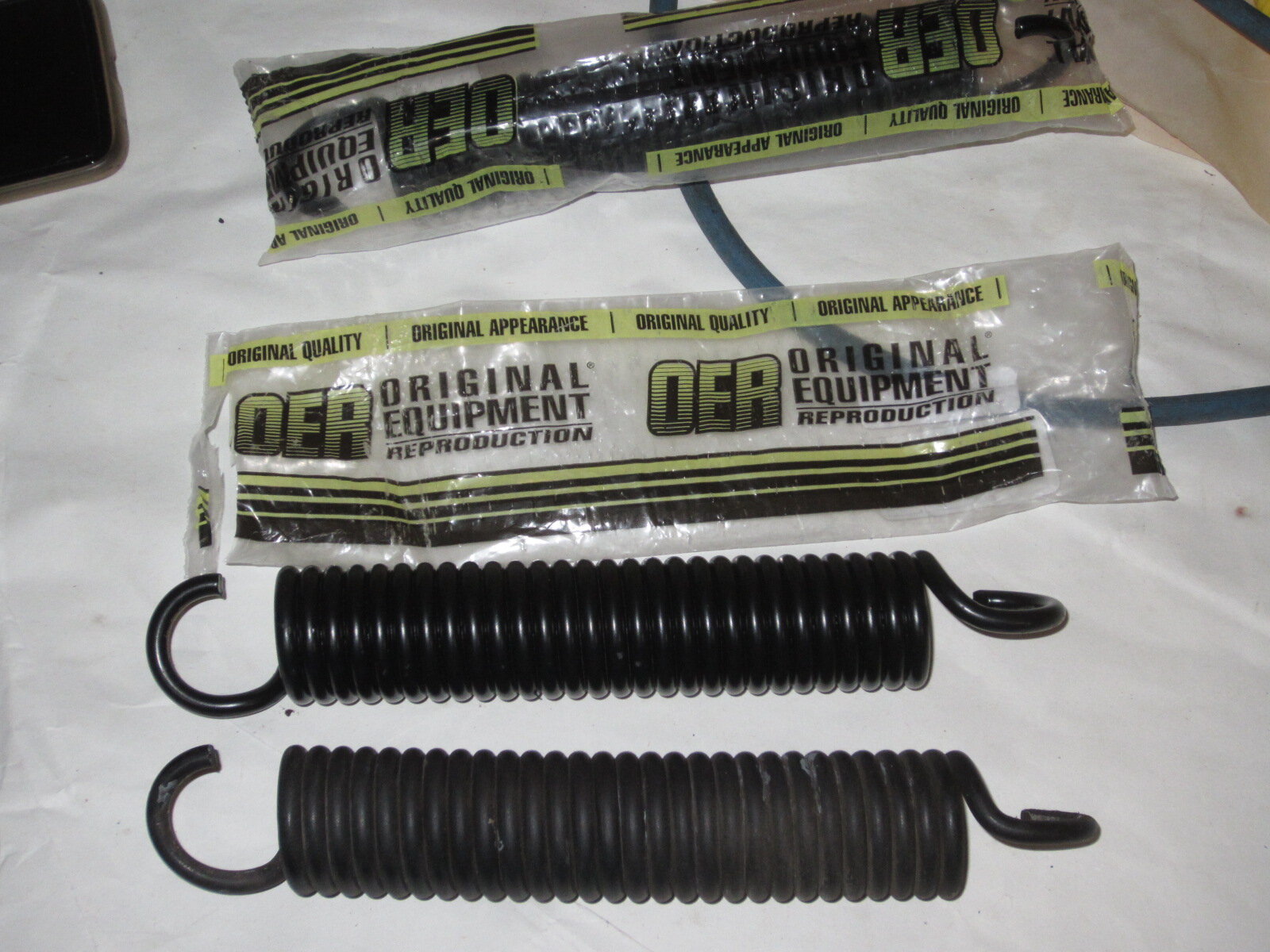
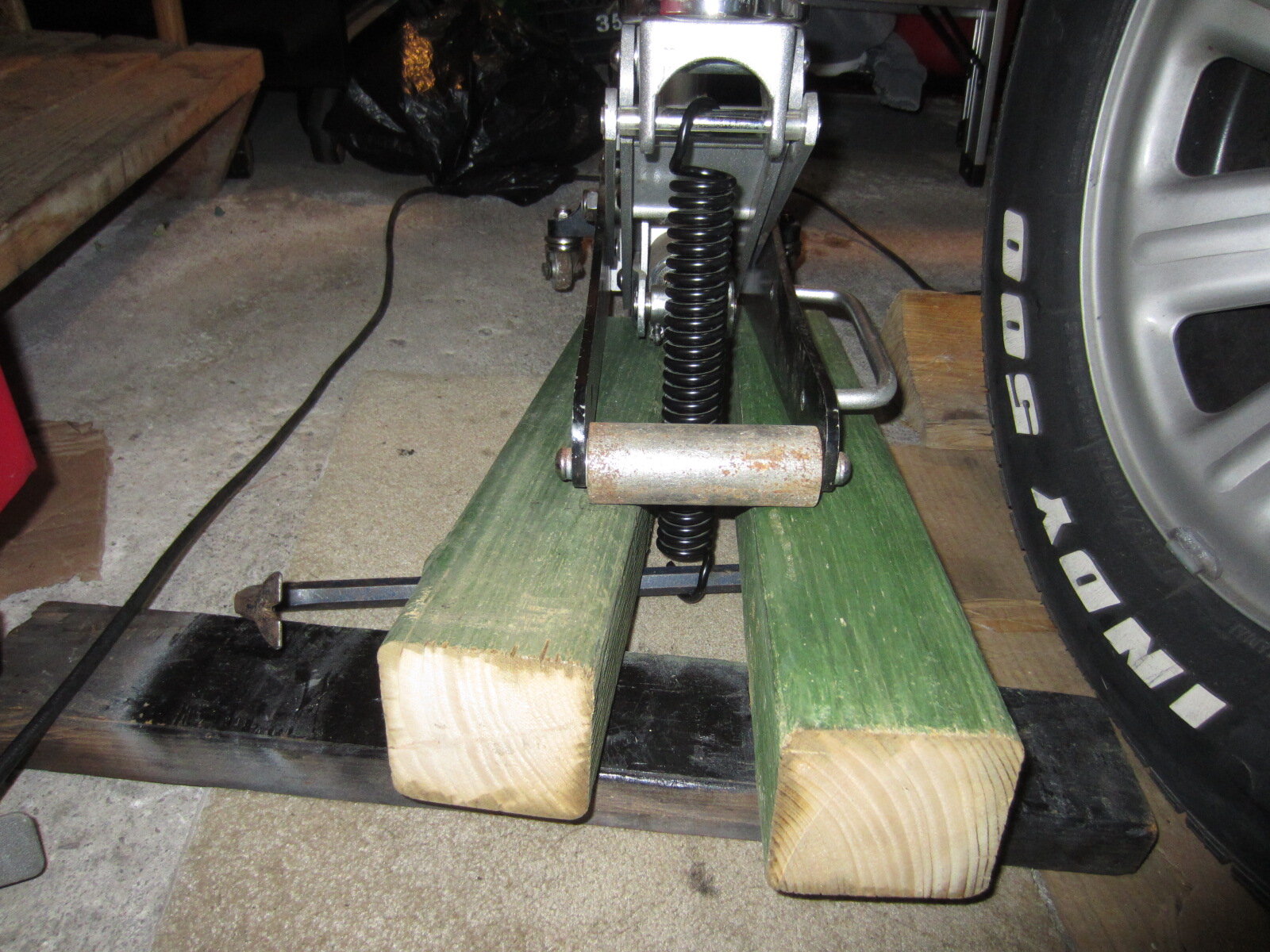
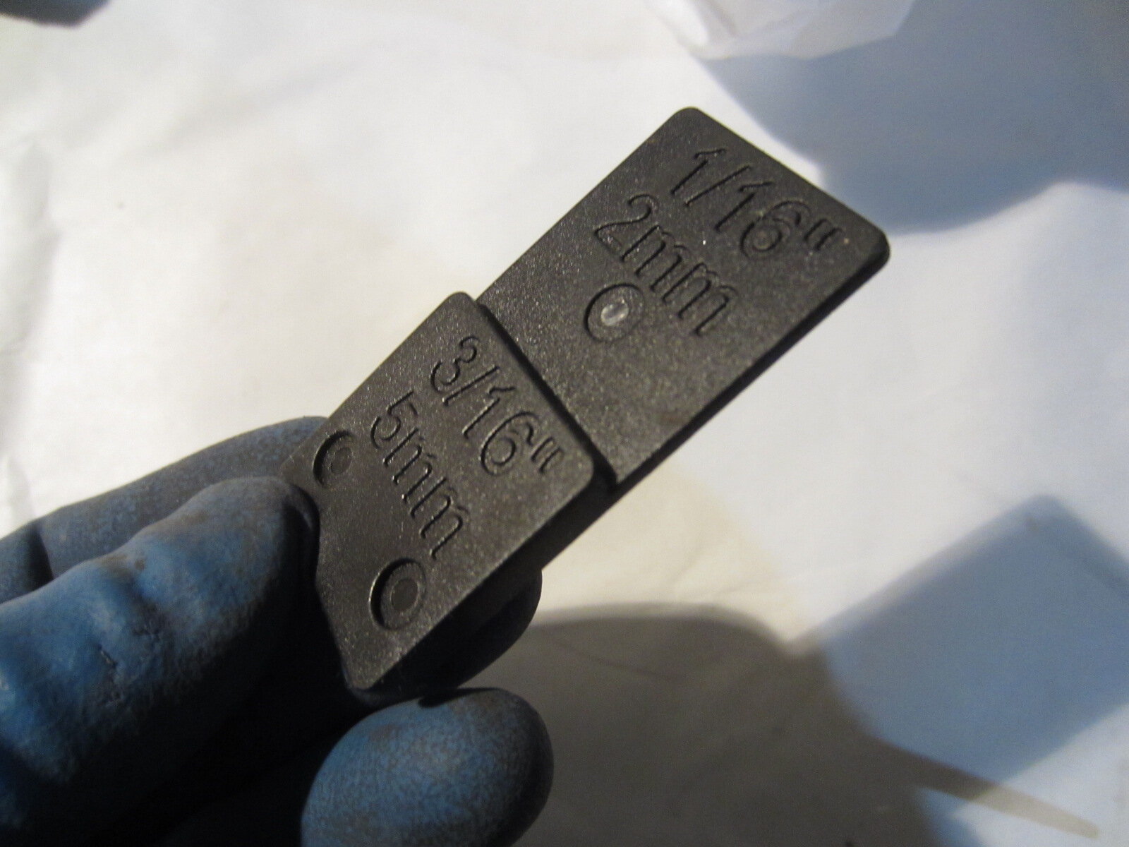
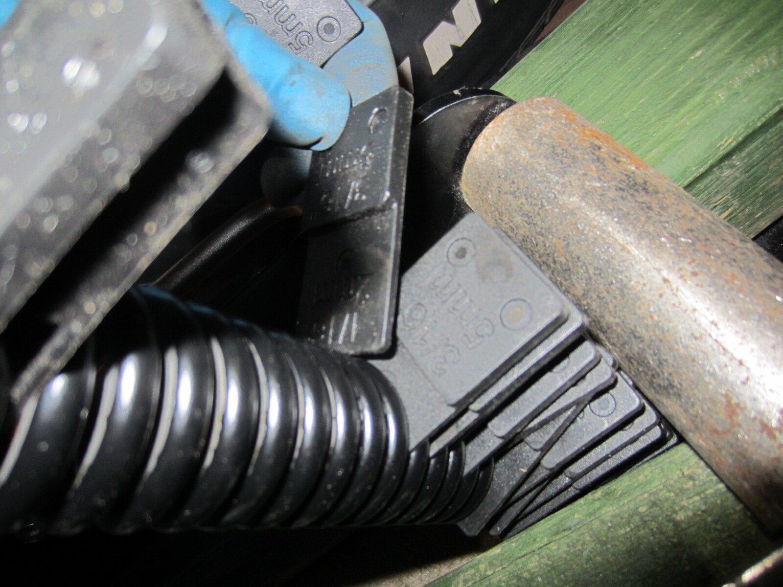
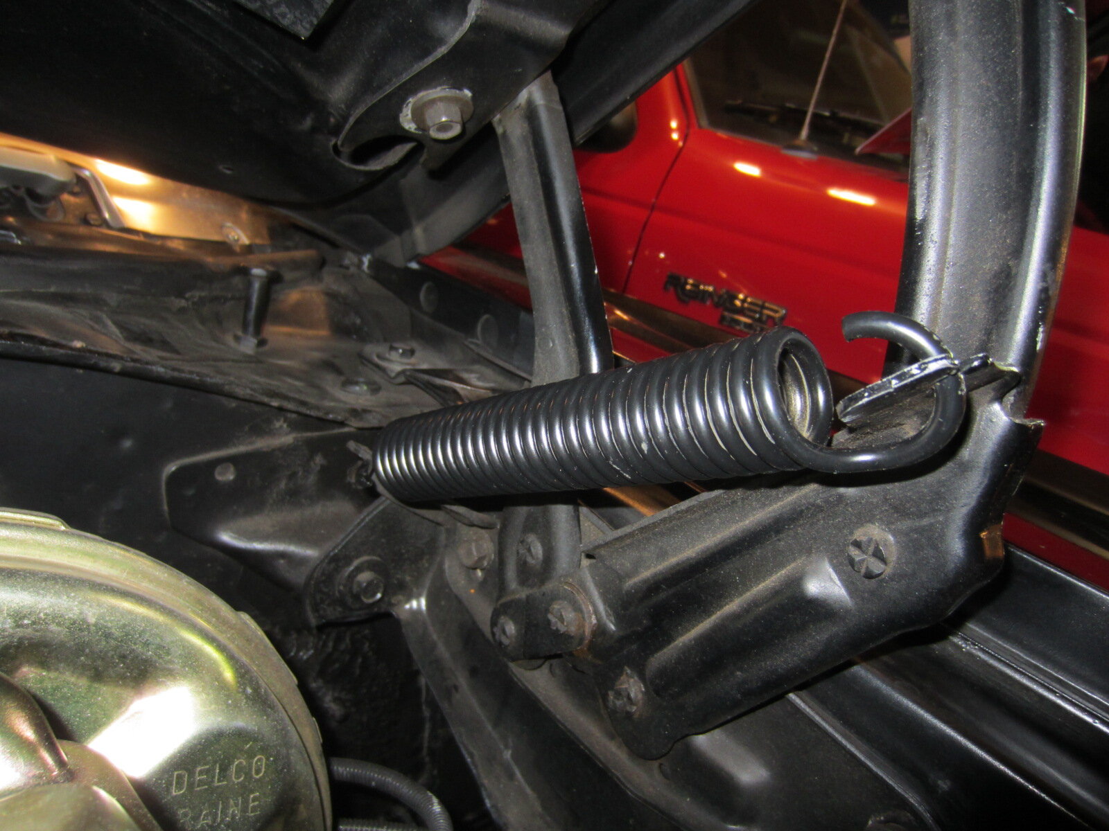
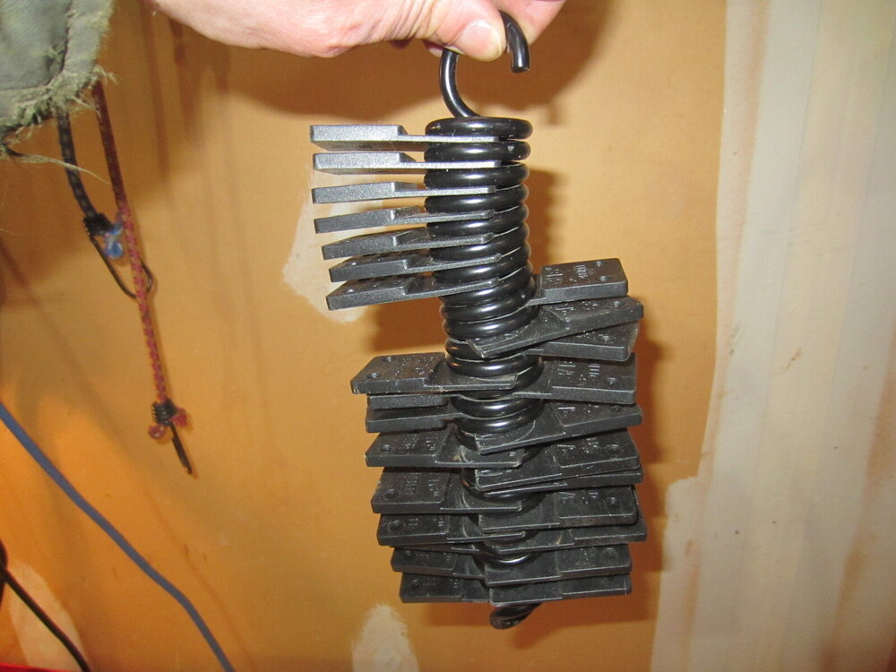
As mentioned on a thread about hood spring part numbers, after a few close calls of almost getting my hands chopped off by a falling hood, I ordered Original Equipment Reproduction (OER) part #3848272 ($17 ea) from Summit to replace my tired 52 year old OEM springs. Total cost with shipping and tax $48.01. The new part looks identical to the original. Installed tonight and big difference. Hood now stays up even when lowered a few degrees from max angle as shown by others' pics on this thread. After considering the many methods out there to replace, I opted for the washer method although for the new springs, I used some plastic spacers I had on hand out of concern of scratching the springs. For easy on and off removal, I found that the spring had to be stretched about 2" from its fully contracted position. To remove the existing springs I let the hood down to stretch the spring while leaving just enough space to stick my arm under the hood to stuff washers in between the coils until the spring was removable without using force when the hood was fully open. I used a broom handle as support to hold the hood fully opened during the removal and installation process. To install the new springs, I used a floor jack (see pic). I hooked one end of the spring under the pin located below the pad and the other around a crow bar I placed under a set of 4"x4" pieces of wood which rested on a 2"x4". The 4"x4" created the additional jack travel needed to get the right amount of spring stretch, while the 2"x4" made it easier to hook onto the crow bar. I also used the jack to remove the washers from the old springs after removal from the car. Once stretched, I inserted 1/16" plastic spacers (see pics) between each coil then lowered the jack. The spacers kept the spring partially elongated. I unhooked the spring from the jack, installed it in the car, put a bag under the hinge, lowered the hood and the spacers fell in the bag. This worked flawlessly for the first spring, but for the second I found I had to add a few larger spacers and then coax some of them out with the hood down low enough to still get reach under the hood. The larger spacers had ridges and that seemed to prevent them from slipping out easily. Using smooth ones like the smaller ones likely would have made this easier. I did not invent the above method but chose it to avoid scratching, prying and because I found other methods did not seem feasible based on the work space, and equipment I had on hand. Hopefully someone finds this useful.


-
PLEASE HELP, Trying to find correct hood springs.
MGD72Monte replied to Blueheeler's topic in General 70-72 Monte Carlo Forum
After a few close calls of almost getting my hands chopped off by a falling hood, I ordered Original Equipment Reproduction (OER) part #3848272 ($17 ea) from Summit to replace my tired 52 year old OEM springs. The new part looks identical to the original (see side by side pic). Installed tonight and big difference. Hood now stays up even when lowered several degrees from max angle. Hopefully they will retain their strength for a long time. I will post some info on removal and installation on a more appropriate thread.
-
Not sure if anyone has already posted this, but stumbled upon it and noted a lot of Monte assembly archival footage. Wish I had a time machine.
-
MGD72Monte changed their profile photo
-
Put in Alpine 4"x6" in the front decades ago. Cut the original brackets so the magnet fits; no issues with the fit on the pax side. To get the driver's side in, unbolted the dash, moved it out slightly, installed the speaker then bold the dash back in careful with contact points to avoid shorting out the flexible instrument cluster circuit. It still is a very tight fit. Good luck.
-
Thanks, very well explained additional info; the taper was clearly visible in those added fittings.