pinstripebob
-
Posts
9 -
Joined
-
Last visited
-
Thanks 1970mcss! I had that traced, but it's good to get a confirmation! RealRed70, hopefully I can try clearing up what I have and what I'm doing. Also I'm not sure why some of my posts repeated themselves. What I have: 1. 1971 Monte Carlo, tachometer car, with damaged engine wiring harness (larger connector shown in post #13 above, second document) 1a. Engine wiring harness had all wires cut or cut & spliced except the tachometer feed wire, repairs are starting nearly from scratch. 2. 1970 Monte Carlo, non-tachometer car, using as a parts car with intact engine wiring harness 3. 1970 Chevelle, El Camino & Monte Carlo GM Restoration Parts Assembly Manual. 3a. When purchased, 1971 was not available and there was no knowledge that the two years have wiring discrepancies. Current status: 1. 1971 forward lamp harness is correct, verified most wires with multi-meter 2. 1971 engine harness has 6 wires confirmed, there are 14 total pins in this connector leaving 8 positions that need to be confirmed. The second document in post #13 above from stangeba shows how the engine harness connector is labeled for each position (e.g. WA, YC, ZB, etc.). I have ZA, YA, ZB, YB, YC, and YD mapped and verified. What I have noticed is the wiring diagrams I have found so far do not 100% match my forward lamp harness or engine harness in my 1971 Monte Carlo. If I could find a diagram that showed the connector such as post #13 above with exactly what wire goes in each connector position, that would be perfect! Good photos showing wire size/color and where it goes in the connector would help also.
-
Awesome! Looks like that helps out with the ignition coil wire!
-
Another thought, a physical 71 tach diagram I have shows a 6 cylinder and this is a V8 car.
-
Another thought, a physical 71 tach diagram I have shows a 6 cylinder and this is a V8 car.
-
Hi Red, Sorry for the delayed response, life has continued to be busy and kept me out of the garage. I am working under the hood only. My 1971 harness at the firewall was cut up badly by a previous owner. The main plug is split into two plugs, one that controls all the lights and similar items and one that powers the starter/ignition/etc. The harness that controls lights and such is now in good shape, confirmed with a multimeter between the under hood plug and fuse panel in the cabin. The other half is not fixed yet. I have a donor non-tach 1970 car and harness, the vehicle I'm working on is a tach 1971 Monte. My struggle is looking at any diagrams I've found on the Internet, including those in this thread, wire colors do not match the pin out shown when compared to either harness I have. For example, the half connector with two extra "legs" that wrap around the other half, pin WA in the corner on the tach 71 is black, but on the non-tach 70 is thick purple. No diagram I have found matches either of this pin. Any thoughts on that would be great! I'm wondering if there are other diagrams for other options I haven't found yet?
-
Following up on this, I have the wiring diagram for a 1971 and 1970. Both of them show some differences between the 2 harnesses I have, mainly where pins are located. Thanks for the diagrams Paul! Here is what I have to be clear: Damaged 1971 harness, with tachometer Good 1970 harness, without tachometer I've moved most of the pins, in fact I've confirmed that the body harness is correct and complete now. I'm running into some trouble with the engine harness, of the 14 slots for pins I have 4 of them confirmed. Is there a wiring diagram that is specific to the 1971 tachometer and another specific to the 1971 non-tachometer that I could get my hands on? So far everything seems to be non-tachometer that I can tell.
-
I should also note that I'm able to remove and replace the pins in the connector as needed. If I can get a solid diagram showing what wires should go in what spot in the connector, I'm good to go.
-
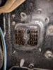
Hi guys, I'm working on a 1971 Monte Carlo's electrical system. This car is a bit of a mystery, it's a 1971 body with a 1972 front end, a 1977 engine (with HEI distributor), and a very hacked up wiring harness in the engine bay. I have a 1970 parts car that I snagged the wiring harness off of. I have a 1971 wiring diagram, but I'm struggling with the connector at the firewall. No wiring diagram that I have seen matches the pinout of either wiring harness, and no wiring diagram matches the pins at the firewall on either car. I've attached a photo of my fuse block connector at the firewall so you all can see what pins I'm working with. No diagram matches this pattern. Can anyone help out, maybe with alternate wiring diagrams? Are there any tricks I can use to figure out which pin should go to what part in the engine bay? Any help is appreciated! Thank you!