LS65Speed
-
Posts
132 -
Joined
-
Last visited
Content Type
Profiles
Articles
Forums
Gallery
Events
Everything posted by LS65Speed
-
Dash Cluster swap (standard to SS cluster with tach)
LS65Speed replied to Alex & Keith 72 Monte's topic in Electrical Tech
That is it. For some unknown reason I had trouble posting a link to that document ????? That is why I posted just the inquiry string I used in Google. -
Dash Cluster swap (standard to SS cluster with tach)
LS65Speed replied to Alex & Keith 72 Monte's topic in Electrical Tech
Thanks for the compliments, "peer review " can be very rewarding! Projects with the car seem to take longer now than they used to and the car sits more than I would like, don't drive it enough 'cause I am always tinkering. The tinkering always takes longer than I planned. Gettin old is NOT conducive to ripping thru projects on the car like I did when I was younger. -
Dash Cluster swap (standard to SS cluster with tach)
LS65Speed replied to Alex & Keith 72 Monte's topic in Electrical Tech
The diagram that JFT69Z provided is the same as the one I referenced with the exception that there are some changes / differences at the firewall connections which are outlined in the doc I directed you toward. You are gonna need those changes also. I think you have all the data ya need now! There is soooooo much info out there but for better or worse it gets lost in cyberspace. Some of the message boards like Chevelles.com have sections that are "libraries" for this sort of info but even then it can be a lot of searching just to find the board with the data. Staring into my coffee this morning and had a thought...we can't be too far apart given Roswell and Kennesaw as the locations of our homes. How about a cup of coffee some morning? Ray -
Dash Cluster swap (standard to SS cluster with tach)
LS65Speed replied to Alex & Keith 72 Monte's topic in Electrical Tech
Typo......."70 - 72.............." not "71 - 72.................." -
Dash Cluster swap (standard to SS cluster with tach)
LS65Speed replied to Alex & Keith 72 Monte's topic in Electrical Tech
Do a Google search on " 71-72 Chevelle & El Camino SS Idiot light to gauge conversion" . That should get ya a PDF file with 4 pages. Let me know what ya think. -
Dash Cluster swap (standard to SS cluster with tach)
LS65Speed replied to Alex & Keith 72 Monte's topic in Electrical Tech
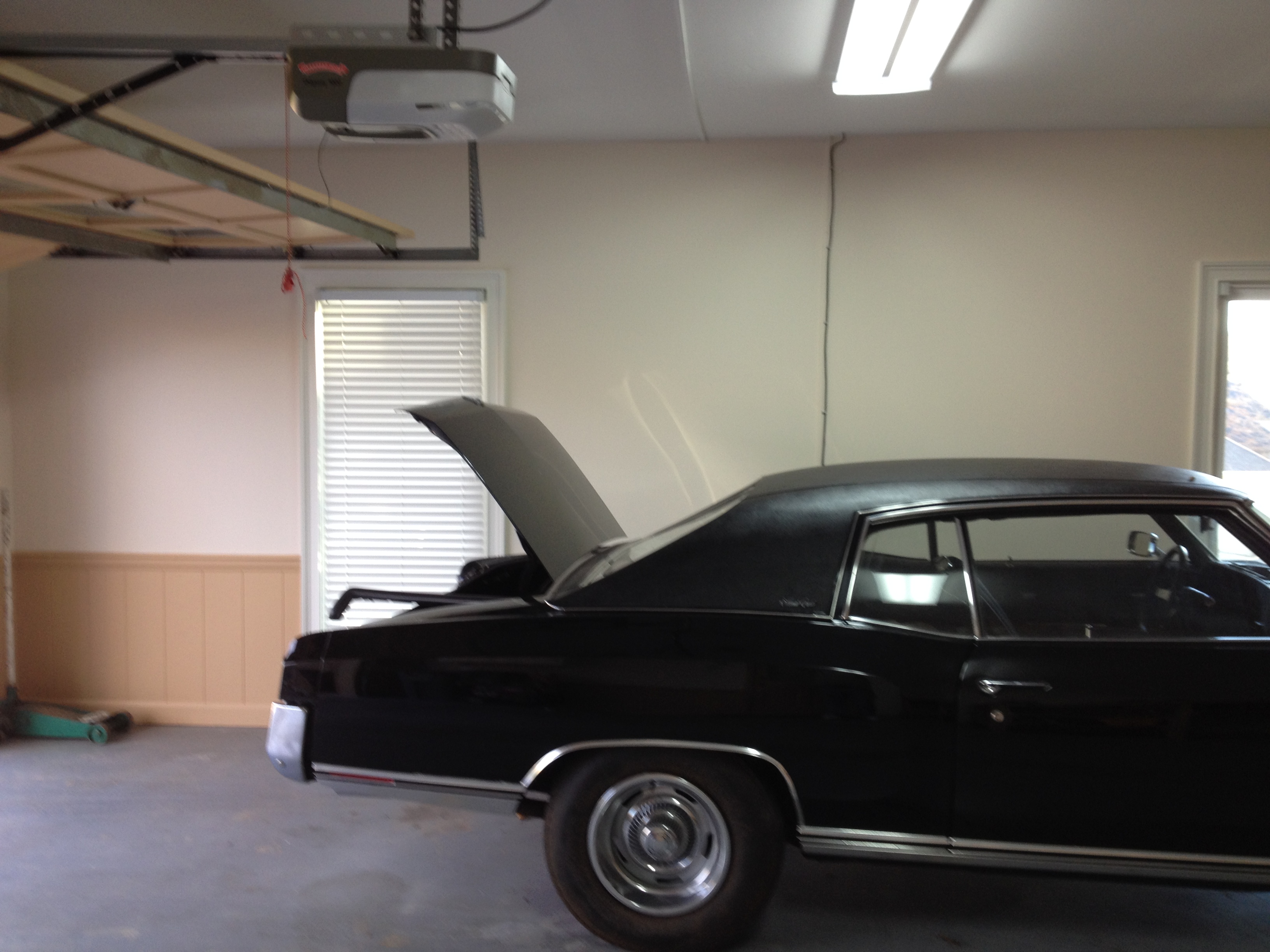
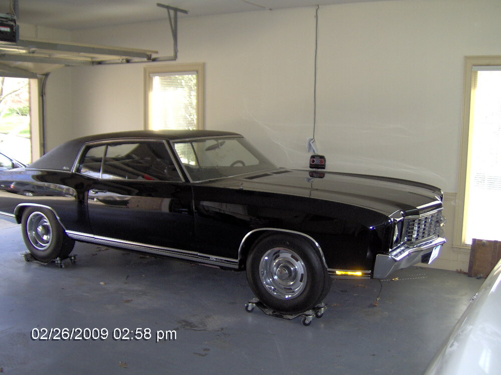
I save everything, the issue is finding what i save. I found a hardcopy 4 page document on just this topic that I had printed off years ago. Now that I know the exact title.... after dinner I will see if it is online somewhere then get you a link. It diagrams the exact pin locations of the connector that connects the dash harness / engine harness to the PCB. You can pinpoint exactly what wire in the harness operates what instrument on your dash with this disertation cthat I have located. I am now questioning my earlier statement about a different PCB for gauge or non gauge equipped cars. It seems there must be two different PCB's but I am just not sure. Should be easy to look at what the usual suspects offer for PCBs and go from there. You are gonna have to change the temp sender for sure but I believe the fuel sender is the same for gauge / non gauge dashes. Car looks great very nice paint and sheet metal. Attached is a pic of my rattle trap. It has been in the garage a long time while I did work on my house and work on the driveline in the car. I really need to get it running and cleaned up. Stand by for a link later tonight..


-
Dash Cluster swap (standard to SS cluster with tach)
LS65Speed replied to Alex & Keith 72 Monte's topic in Electrical Tech
I had some time this morning and started looking into this, maybe just to verify that my memory still works? Anyway there was a drawing that used to be on the web in several places that mentioned changing wire locations at the firewall connector. Can't for the life of me find it today. I can see it in my head but the detail info it contained.....can't recall all that. It has to be out there somewhere but I have yet to run into it. What I did learn.... The 1972 wiring is different from both the 1970 and 1971 MC's in several places. You cannot plug and play your existing printed circuit for a non gauge car with the gauges your buddy gave you. You gotta get the correct printed circuit for the gauges. Some threads on various boards indicate that harnesses under the hood need to be changed also. Look at the attached. It is a post by a fellow named Donny at American Autowire. This is Chevelle data but it is applicable to MC's Just wanted to give you a heads up here. The dash harness from your sweep dash will NOT work and cannot be made to work. It is 100% different in construction and design from the SS gauge dash harness. Even the standard dash harness for the SS cars with round pods and warning lights is different. While similar looking, there is also a common mis-conception that the 70-2 dashes are the same. That couldn't be further from the truth. Aside from the color of the numbers and letters being different (green vs. white), the harnesses on the cars are also very different. When compared to a 70, the 71 is somewhat similar, but the 72 is not even close. You will also need to change your front light harness as the wires fro the amp meter are spliced in parallel to the charging circuit. You cannot just "add" amp wires as there is no external shunt in the system and the guage is manufactured to read the current over a given length of wire. The GM documents tell you right on them to not change the length of the amp meter wires in either the front light or dash harness or the gauge will not read properly. Also, be aware that the aftermarket gauge set available has the amp meter wound backwards and when you hook it up to a new harness the gauge shows a discharge instead of a charge. Hope some of this helps. Not sure this helps or discourages you but "knowledge is power" as the saying goes. -
Dash Cluster swap (standard to SS cluster with tach)
LS65Speed replied to Alex & Keith 72 Monte's topic in Electrical Tech
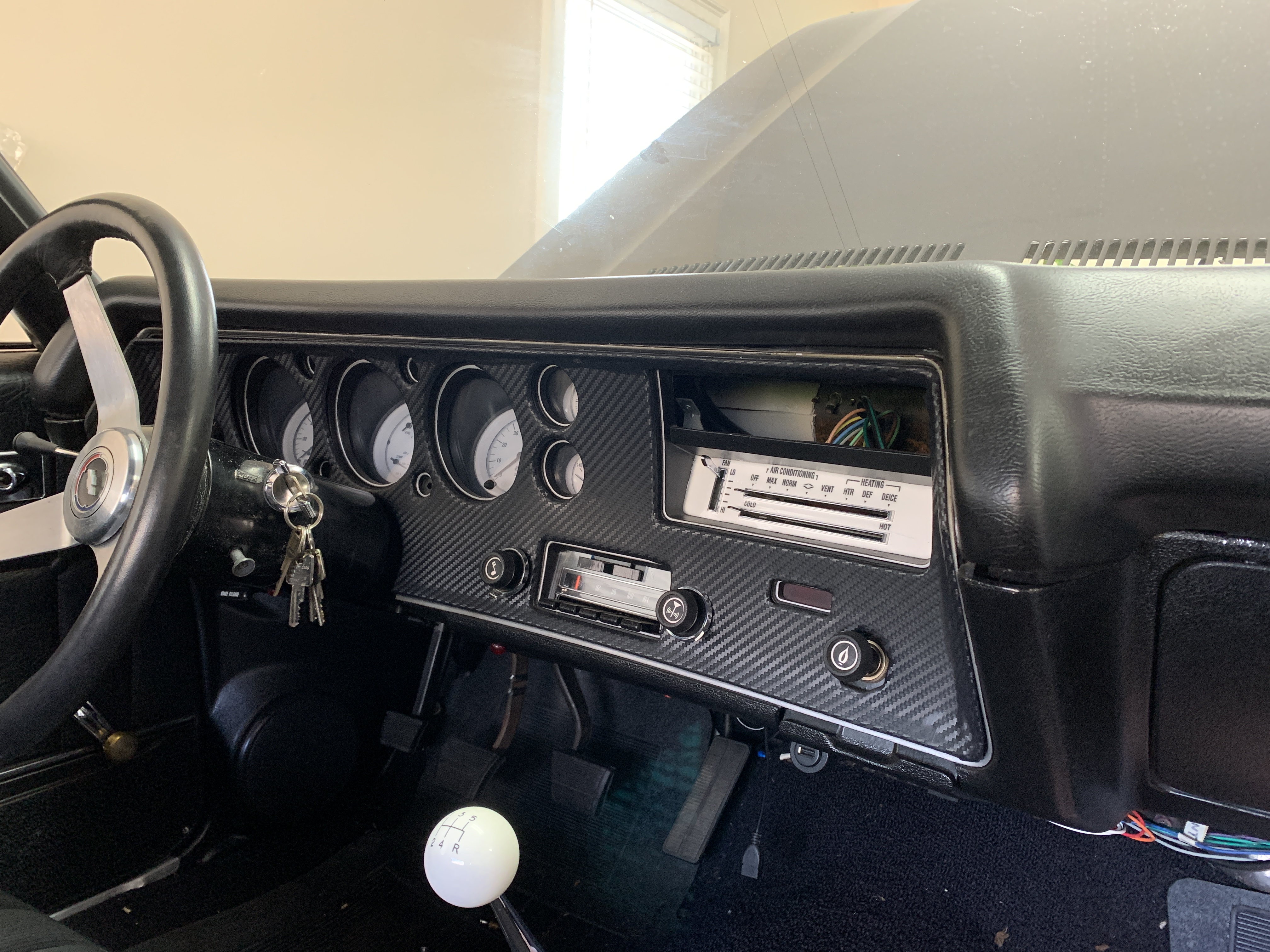
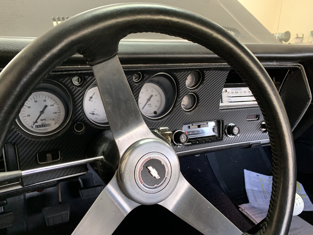
Hello Neighbor! I see you are in Kennesaw, I am just East of you in Roswell ! I did a similar swap many years ago and although I cannot recall the specifics I recall that in order to make the swap there are a couple of wires that need to be repositioned at the fuse panel engine harness junction if you want to run the factory circuit panel / circuit board from gauge equipped cars. After that it is all plug and play I think. Thinking back the change was as simple as "move wire X from position 1 to position 3 and move wire Y from position 3 to position 1. That description is based on a years old recollections but it really was a simple task. The specific info is out there on the net in various places and I believe it is in an Archive area on www.chevelles.com. I have long since changed out my gauges to a resto mod sort of vibe since I did what you are planning otherwise I would be able to give you more info just by crawling under my dashboard. FWIW here is the dash as it sits today.....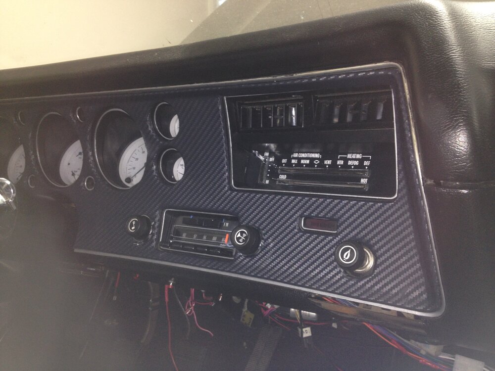

-
Unfortunately if the clock works right during the test you come away w/o knowing what the issue is within the car.
-
Why don't you connect the clock to an external 12 volt battery that is not otherwise connected to the car. Only supply power to the new clock and eliminate all other potentials problems / issues. If it keeps time correctly you know there is an issue in the circuitry of the car as opposed to something being wrong with the clock.
-
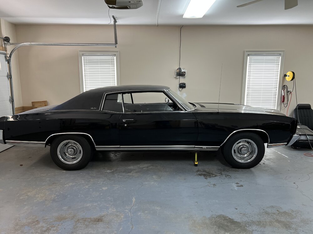
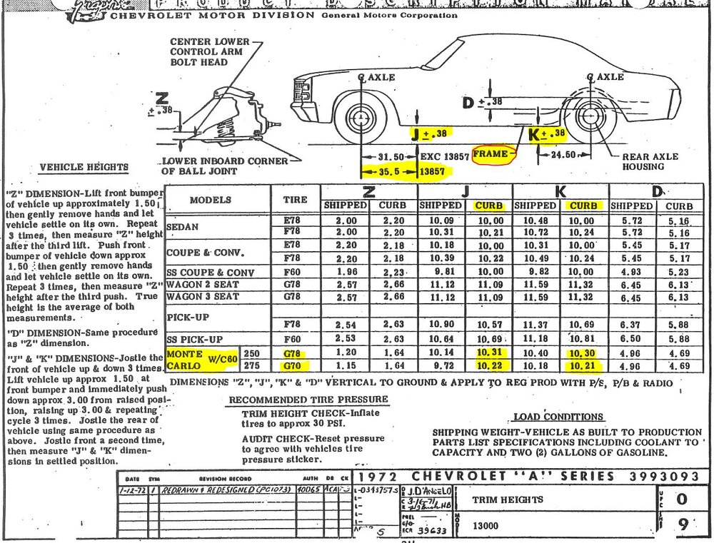
Ok, before saying anything else i want to thank everyone who chimed in on this thread. The data, info and pics you guys provided have given me an idea what I am going to do. As the refs say during questionable calls during NFL games: "Upon further review the play stands as called"! I am going to leave it alone. In the pic below you can see a tape measure which tells me the ride height height is very close to the dimensions specified in the Assembly Manual. So that is where it's gonna stay. I must admit it still looks high to me but the numbers from the floor to the frame are the within a small fraction of numbers from the chart. I don't know what spec springs are in there and unless I have a change of heart those springs are going to stay in there. Thanks again to everyone who chimed in!
-
Of course but they are good enough to show how far out of the ballpark I may or may not be. What I did learn just by reading the numbers is that the cars originally were more or less level front to rear. What started me on this wild goose chase was my dislike of the cranked up look for rear ends on Monte Carlos. My goal is more centered on the front to rear numbers for my car and for a stock factory car. If I am a bit higher both front and rear or a bit lower both front and rear when measured against a factory car that is gonna be Ok.
-
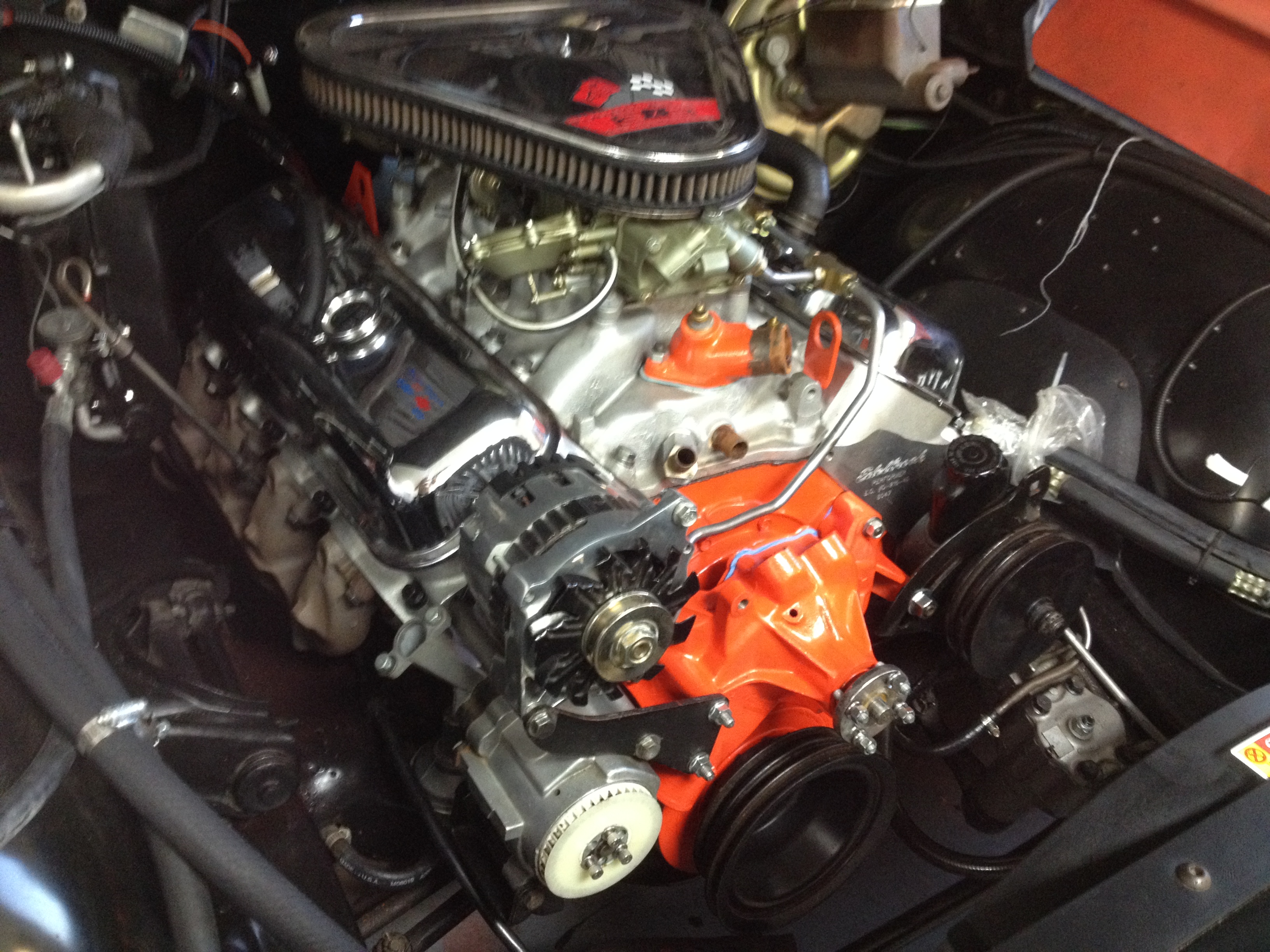
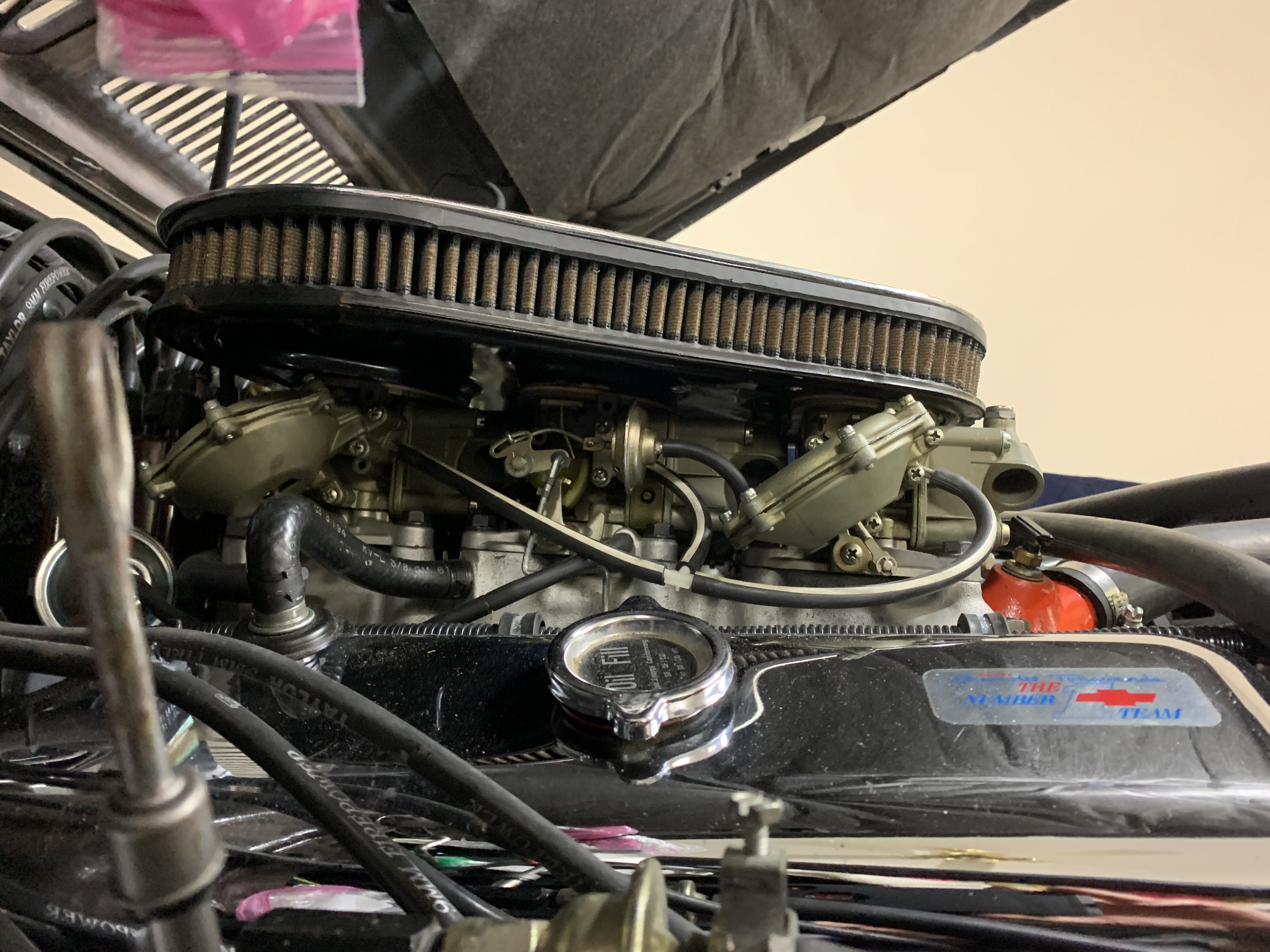
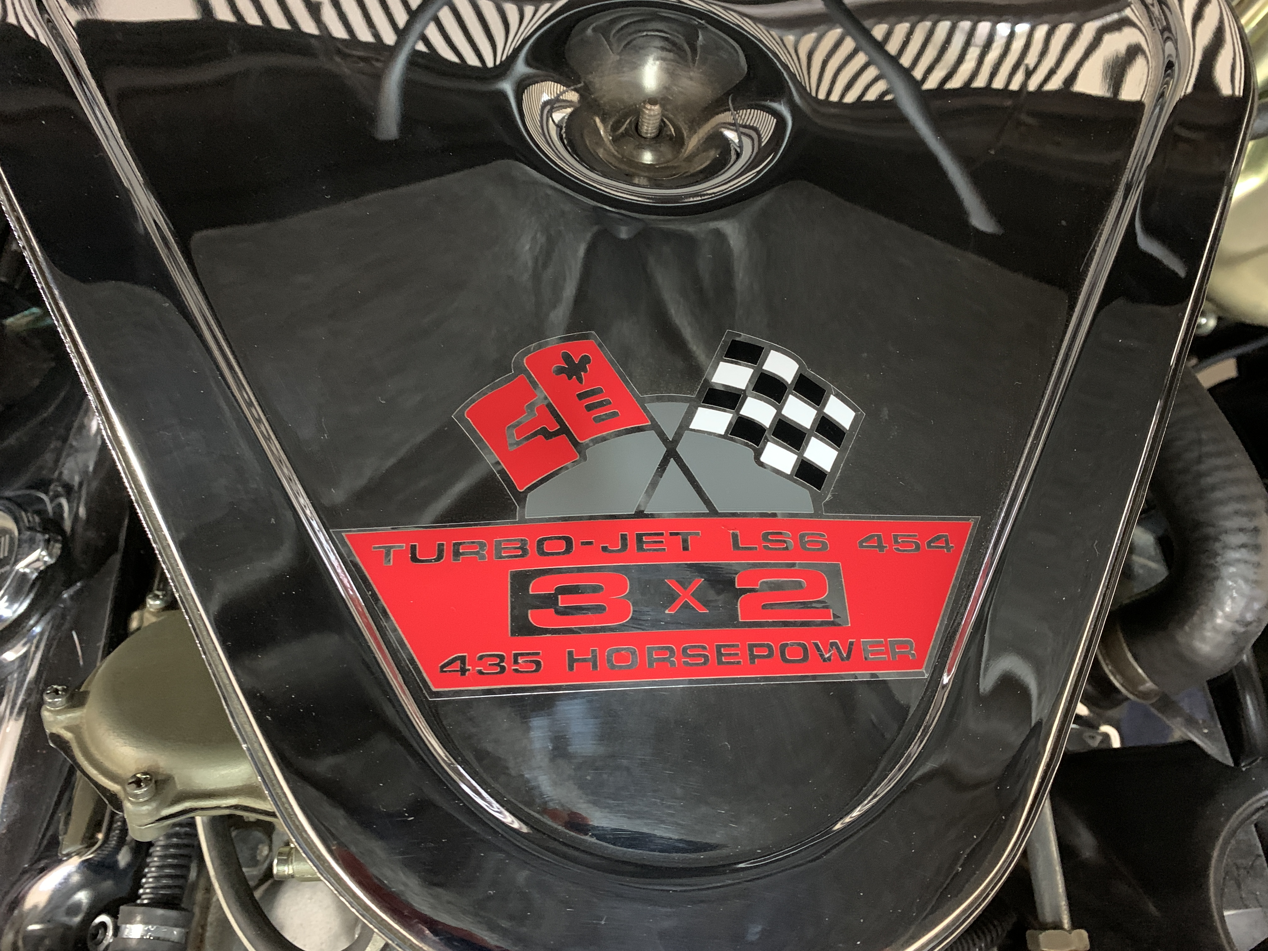
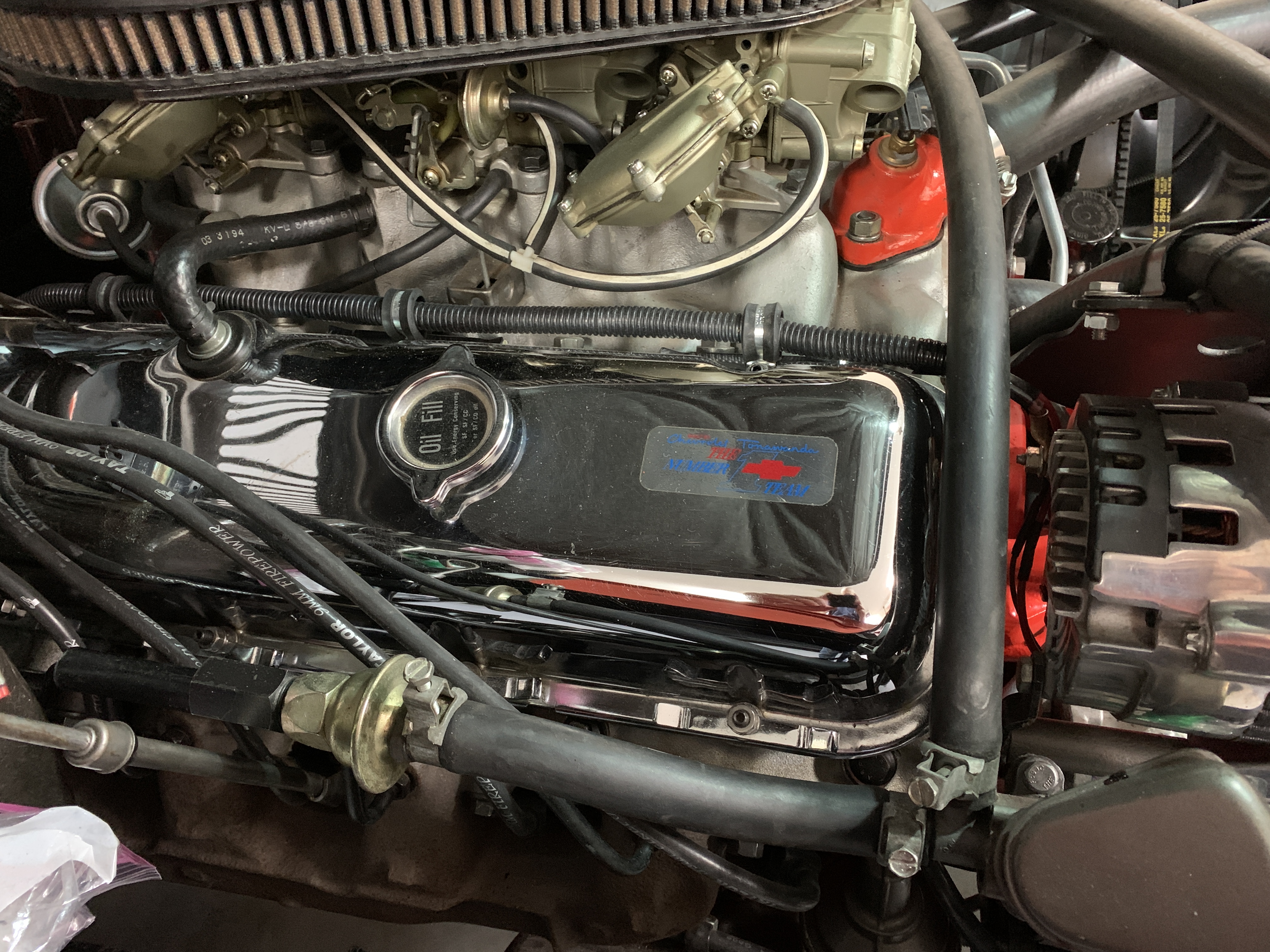
I think you might be mixing two different posts together Mike. My bucket of bolts is a 454 with the 67 Vette 3x2. James has the 427.
-
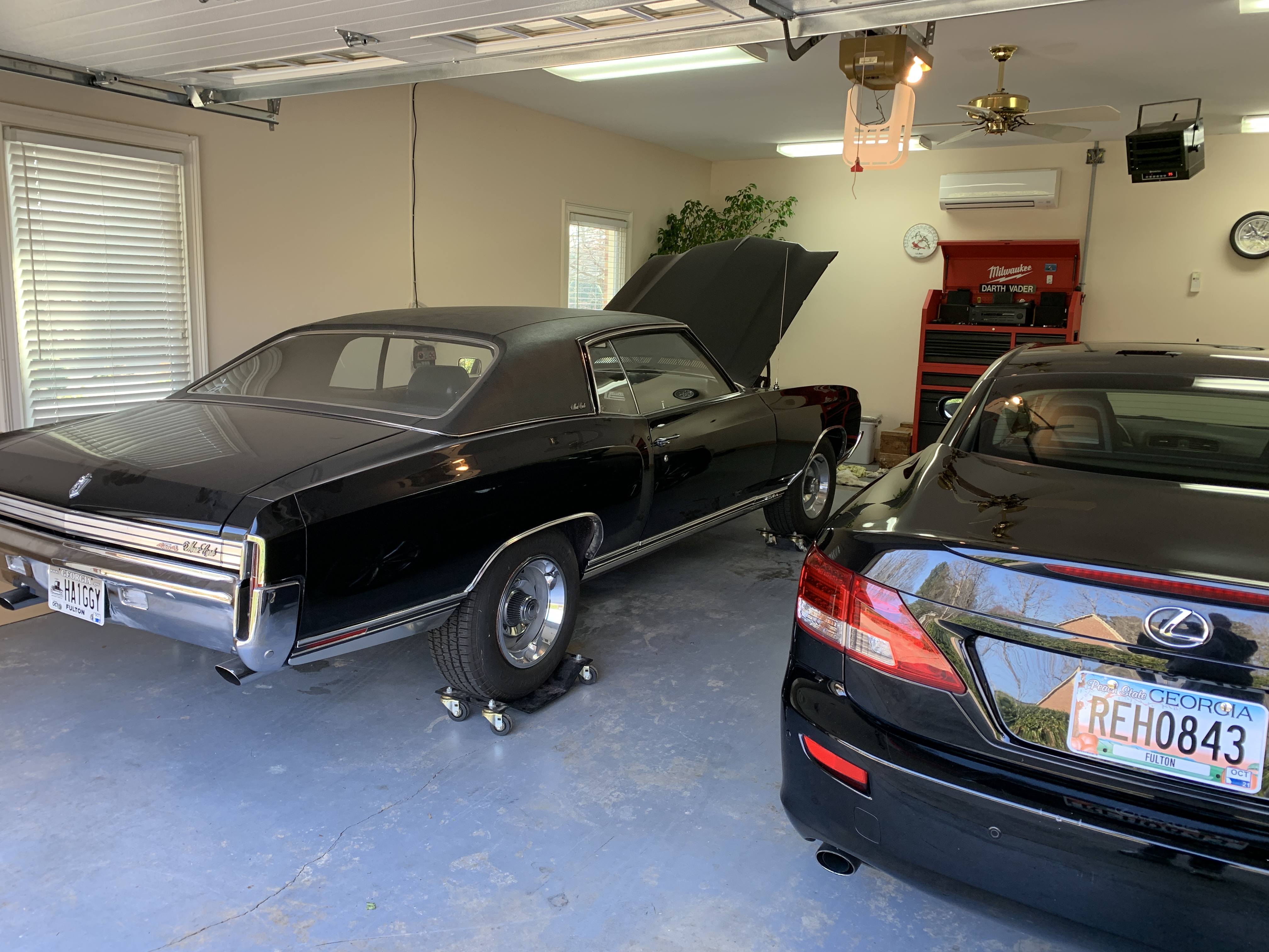
Yes the scoop at two inches looks great grafted onto the stock hood. The 4 (or even more ! ) inch units are just a bit too much for me. That said "to each his own" is what this hobby is supposed to be about. My thoughts on this stuff are nothing more than my personal feelings. Thank you for the compliment on the car, I have done a lot of modifications that you don't see from the outside. My goal is a stock appearing exterior with modifications to build the car GM could have built using era correct off the shelf parts as well as modifications like the 5 Speed that the aftermarket later introduced. A couple of under the skin mods are pictured below......


-
I am doing a hell of a job on these replies....first I proved I can't read and then I demonstrated I can't type!!!! LOL!!! Geeze!!!!!
-
First of all I like the hood you are running. The height is just right to my eye. Some of that design aftermarket hoods are a bit too prominent when they are taller than yours. Your car appears more or less where mine is now in the rear as I look at the placement of the fender lip molding relative to sidewall of the tire on your car. The first posted pic of my car up above has a more level look than what I am seeing after the 9 inch rear went in. I think my desire to get a bit lower profile comes from the overall profile of the Monte Carlo with the long hood and short deck. The Chevelle hood / deck dimensions work better for me with a slight elevation of the rear on the Chevelle as opposed to the Monte Carlo front / rear dimensions with a slight rear end elevation.
-
That could work, might be a bit lower than I want but knowing a dimension from your car would help me sort this problem out. Would it be too much to ask you to get a measurement ? Whatever works for you as long as I can easily translate what you measure to the same location on my bucket of bolts. If possible the "J" and "F" dimensions on the chart posted above would be great.
-
Hello John!!!!!!!!!!! How are ya doing? Did you ever change that console? What else is going on with the car? Interesting comment on your part. When I loaded the 9 inch in the car had no gas and no spare tire in it. It clearly was WAY up height wise. I even called the supplier of the 9 inch and did some gentle squalking. As I measure it now, against a factory 12 bolt, the perches are pretty close between the 9 inch and the 12 bolt. Maybe 1/2 inch between the two. Right now it is sitting with 18 gallons of gas in cans in the trunk and a 15x8 wheel with a spare tire in the trunk. I think a slightly lower look as in the post next to yours is what I want to get to. Gotta go, my Black Lab is dancing around here asking for his walk. More later, keep in touch. Coffee some day.......?
-
Should add that the first pic is where i want to get it. Maybe even 1/2 inch lower.
-
Not the best full side pics but here are a few. The 9 inch Ford install seemed to push the back up a little, I think because the spring pads might be just a bit higher than the factory rears. That said as I look at these pics I find myself wondering if this set of "push ups"related to the springs is necessary. None of the attached have the 9 inch rear installed. I want to get that trim around the wheel opening a bit further down on the siodewall,


-
Lemmie check...stand by.
-
The car is a mongrel so this is a tough task. Its a 454 (LS-6) but it has aluminum heads so that is -70 LBS off the front wheels and an aluminum 3x2 Vette intake (don't know the weight loss but it has to be lighter than the cast iron 4bbl intake. It also has factory A/C but it has an aluminum aftermarket compressor. Laastly it has an aftermarket 5 Speed that I suspect is close to a TH350 trans, maybe slightly less weight. It is running a 9 inch Ford rear that is the same width as the 65 / 66 / 67 Chevelles and has 15x8 Rally rims on the back. It is running 235- 70 15 tires right now. I am not gonna kill myself trying to squeeze the absolute largest tire possible under there. They look good with large tires but I cannot see myself swapping wheels and tires for a minimal extra bit of road contact. My plan is to see where it sits compared to stock using your data and go forward from there. I think the rear is a bit higher than stock and I am guessing the front is possibly a bit lower than factory. I have had the car forever (and I do mean forever). Front springs are HD SBC springs from the days when it was a 350 W/O air but with the weight taken off the front end by the aluminum BBCc parts I am betting it is close to the weight of a stock cast iron SBC. The trick is gonna be determining how much of a drop from the current height will be achieved with a given set of rear springs.
-
Looking right at it and missed it! Shame on me.
-
Joe Thanks to you again! I do however have another question that needs to be answered in order to use the info you provided. Are the numbers quoted in columns "J and "F" measured from the ground to the frame, to the lower rocker panel, to the top of a piece of trim or the bottom of a piece of trim? Might be I am missing something that is right in front of my face. It wouldn't be the first time I did that. Maybe the assy manual has a footnote that is not on what you supplied to me? Maybe the info is right in front of me as I just said! Can you help out with this question? So far I have concluded that the cars sat approximately level bu looking at the numbers on the chart but I can't yet relate the chart to what is sitting in my garage. Ray
-
Looks like there might be a typo in your link? Post after yours looks like it will give me what I need. Thank you!