


A_Rescue
-
Posts
81 -
Joined
-
Last visited
Content Type
Profiles
Articles
Forums
Gallery
Events
Posts posted by A_Rescue
-
-
I own a 1971 monte 454SS. Does anyone know the brake type used on this vehicle. The book shows 4 versions, Delco Moraine Single or dual diaphragm, and Bendix single or dual diaphragm. I am not able to look at the car today and I am hoping to get the parts on order.... or a rebuild kit for the diaphragm and master cylinder
brakes idiot light on and brake fluid seeping on the diaphragm outer case from master cylinder
Thanks... John
-
Thank you Paul…
john
-
If the cooling system is functioning and the gauges are intact... check the ignition timing....
john
-
The drivers seat doesn't have the forward/backward electrical switch, I am having a hard time finding anything for the electric seat... motor, connectors, or the switch....
Anybody know what the pat numbers are or where I can find them??
Thanks
John
-
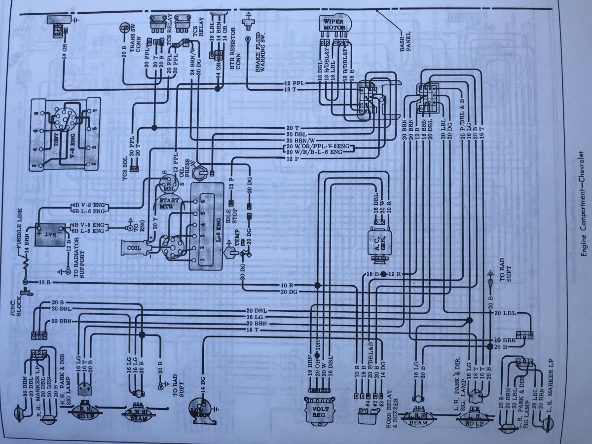
Paul, I am looking at the 71 ss instrumentation panel schematics and I can't seem to be able to locate the ampmeter circuit… any clues? The ampmeter is pointing to the floor and doesn't move... might be disconnected, unwired, or broken...
clues are appreciated
-
The single wire versus the 3 wire alternator essentially means that the voltage regulator "Senses" the voltage level at a point downstream of the alternator, versus right at the alternator. For low current draws systems (No fans or electric fuel pumps or a high wattage stereo) this is not a problem. What can be done is reducing the wire losses between the 1 wire internal regulator to the distribution/fuse panel for the the DC distribution. for the 1 wire alternator a heavy Ga. wire to the fuse panel will decrease the drop in voltage in the wiring and the local regulator on the alternator will do a better job with only a 1/4 volt or so difference between the regulator sensing the voltage at the alternator compared to a 3 wire sensing the voltage at the distribution point... Make sense?? decreasing the voltage drop to the electrical loads will be as effective as 3 wire remote regulation.....
john
-
-
Ten Ga. wire is a better choice. The factory wire is sized for the average current and disregards the peak voltage drop of the "Pulsed" coil primary. So the average current is what the factory wire size is determined by, but the peak current losses are what needs to be limited for maximum performance. Keeping in mind the average current in the wire is determined by RPM's and the peak current is always determined by wire resistance and the dielectric resistance of the compressed fuel/air mixture.
The voltage drop across the wire during the "Pulse" is calculated by peak current x peak current x wire resistance. The peak current losses (Voltage drop) will be the same every current pulse but the average losses (Voltage drop) will increase with RPM's.
minimizing the wire length and resistance (Thicker wire/smaller Ga.) from the HEI to the coil primary will give you the strongest spark. The thicker Ga. wire has lower resistance and becomes more critical as the compression of the motor increases. The higher the engine compression the greater the "Dielectric resistance" of the fuel/air mixture becomes... so a smaller gap at the plugs and increased wire Ga. and minimum required wire length becomes more significant... Higher the compression the higher the dielectric resistance and the smaller the gap should be.
If you use crimp lugs I recommend "Tinning" the wire with a soldering iron prior to crimping, then after crimping the tinned wire in the lug, solder the crimped wire to the crimped lug. The slow effects of corrosion will take it's toll in time, increasing the voltage drop as the inevitable oxidation occurs. So, the normal (Untinned) wire to crimp lug connection, in time, will exceed the wire resistance losses and slowly degrade the spark. Also, when tinning the wire, make the solder go to the heat, place the solder iron on the tip of the wire and place the solder near the insulation and the solder will wick towards the iron and wont migrate under the insulation of the wire.
john
-
Thanks Stephen, nice set up Ian... Ian, any cooling problems when loaded? and they both pull about 3500 cfm?
john
-
A lesson learned with fuel injection tuning... If the motor is built and the vacuum is altered.... The PCV valve requires changing. The stock "Tapered" PCV will oscillate open and closed and make tuning below 2000 RPM's a series of over compensation. Straight wall PCV is required and meters correctly at lower vacuum...
john
-
willie this should help....
john
-
hello all
looking at electric fan kits fr a 71 monte SS BBC with 650 HP. So many options between 200 and 500 bucks its hard to know what is and isnt effective. Anyone with a reliable electric fan set up want to chime in? the EFI controller I am leaning towards gives me a 2 fan option with fan relay control at selectable temps. Some fans offer an autonomous temp control and some don't. Not sure if I need variable speed controller with two adjustable fan on/off built into EFI controller
Whats working for you guys?
Thanks
John
-
Thank you dan and Cody, I will document what and where I get what is needed. I prefer to make my own harness and route it as required, so the connectors are important
Thanks a bunch
-
Thanks Mo, norwalk huh.... harbor city here
-
Hello All
I have a 71 monte ss454 and I am rewiring it. Does anyone have a listing of the connectors required for trunk, interior, and engine compartment?
A kit would be crazy good
john
-
Anyoe have experience with this system, if it works well and is reliable I will keep and clean the stock fuel tank...
-
ya.... 496.... I love big blocks... good for you!... have to change your moniker from 420 ponies to ??? BTW... That jack nicolsen photo cracks me up every time I look at it
john
-
I shot Carl an email late last night and a thorough response was in my email q before I woke up, excellent customer service!
Below is the email and his response. Yes using the MAP sensor has benefits... electrical load reduction and extends the operating range of the injector when lowering the fuel pressure at cruise/idle. That means the injector minimum pulse width stability issues for high LBS/HR injectors are less of an issue since the injector duty will be higher at lower pressure....
I added an additional few questions about the pump motor type best used in PWM systems and any conducted garbage emissions coupled to the 12 volts system. (Valuable lesson learned from an early generation LED upgrade headlight on my Harley interfering with PCM)… long story, I removed the lights...
My query to Carl
I am very interested in your product and wish to ask a few questions.
Is there a particular type of pump motor to use for the PWM drive voltage versus the DC drive voltages? If so, what EFI pump tank motors do you recommend. I am converting a thirsty 1971 monte carlo 454 to fuel injection and want to put an efi fuel tank/pickup/motor and control the motor with your controller.
Conducted emissions on the DC lines, are the input DC lines filtered and isolated from the PWM, if not, do you know what the PWM frequency is?
MAP feedback advantage over Constant pressure is a reduction of steady state load on the electrical system... True, do I have this right?
thanks
johnReply from Chris
Hello John, and thanks for the inquiry.
Depending on the horsepower level there are several GM fuel modules that should work well. The Gen5 Camaro fuel modules, the SS and ZL1, may be good choices. A specific mounting ring is needed.
In general, the turbine style pump used in a fuel module arrangement is best for returnees PWM fuel delivery.
Simply attaching a turbine pump to a closed loop control system typically will result in poor low duty cycle performance. Some fuel beyond that used for idle/ cruise must pass through the pump.for smooth operation. In the OEM fuel module this bypassed fuel is used to power the suction transfer pumps to keep the lower reservoir full
PWM output frequency is approximately 1khz.
MAP reference fuel pressure has several advantages. Power reduction is one. For very large injectors a lowering of the idle/cruise fuel pressure allows for sufficient duty cycles to allow good fuel control.
Regards,
Carl Casanova
VaporWorx
805-390-6423
-
I think I found the answer in a tech write up. manifold methods draws less steady state cruising current than the constat pressure syste... longer life/higher reliability and colder gas.... cold gas is good
Another feature of PWM control is the reduction in the electrical requirement. For example, the 5th-generation pump requires 10 amps to run at full speed at 58psi. At cruise the PWM systems requires approximately 3-5 amps depending on if the system has a manifold referenced or static fuel pressure. This reduction in power also means greater alternator life.
john
-
Paul,
I see that the vaporworks PWM fuel pump controller gives a choice between MAP sensor feedback or Constant pressure feedback. At first thought I am thinking the dynamic response of the MAP sensor feedback controlling the PWM will respond better. I am not sure if the response time of the map or the constant pressure regulator method would make a difference. I am thinking the Constant pressure is best for self learning EFI systems... Which method did you use? You think there are any advantages in one method or another?
Thanks
john
-
Wow, good story.... Thanks Steve.... Now Im gonna have to find some old photos at Danbury state fair circle track rolling tires around the pits for Chicky Stockwell in the 7/11 jalopy circa 1970....
Thanks Steve
-
Thanks a bunch, you guys are great!... any thoughts on a single plane or dual plane EFI manifold (60 lbs+ injectors)? I am going to dive into the different software packages with the EFI controllers and examine the VE tables and make sure I can get fine resolution, hopefully 256 RPM increments from 500 to 2500 RPMs and 0.5 lb. resolution for the vacuum rows of the VE table , that would be 8x 25 effective rows of VE tuning capability to tame the idle and low end drivability... which may make a single plane meet my needs.... maybe....
Once again I appreciate all the feedback... Paul, now I'm thinking of a PWM controller on the dual electric fans too...
john
-
I have stainless custom mades, but I have been told Hooker does well. My only suggestion is to weld low profile 18 MM bungs in each collector. Put plugs in them for now. The ability to put a wideband O2 sensor system in each collector for monitoring, tuning, or troubleshooting is worth it's weight in gold... Hopefully you wont need them, but if you do... they are there. The bung should be located between 3 oclock and 9 oclock, preferably at 12 oclock.... Condensation will destroy the wideband...
john
-
correction... I think the kit will be a little over 5 grand.... eeek....
Brake cylinder type
in SS 454
Posted
Thanks willie... Fixed it... master cylinder leaked into booster... cleaned it all up, new master cylinder... bleeding... then booboo gone
Thanks