B-Man
-
Posts
117 -
Joined
-
Last visited
Content Type
Profiles
Articles
Forums
Gallery
Events
Everything posted by B-Man
-
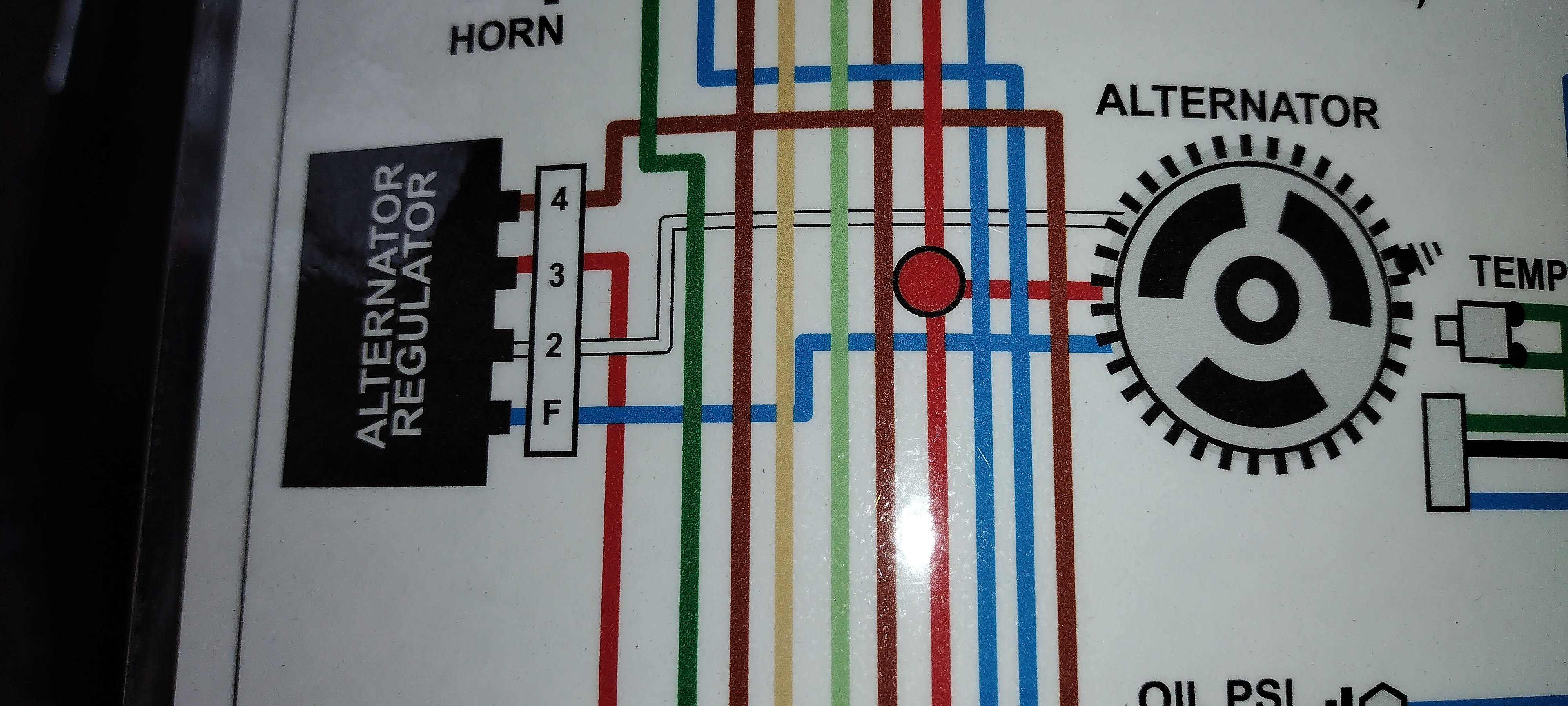
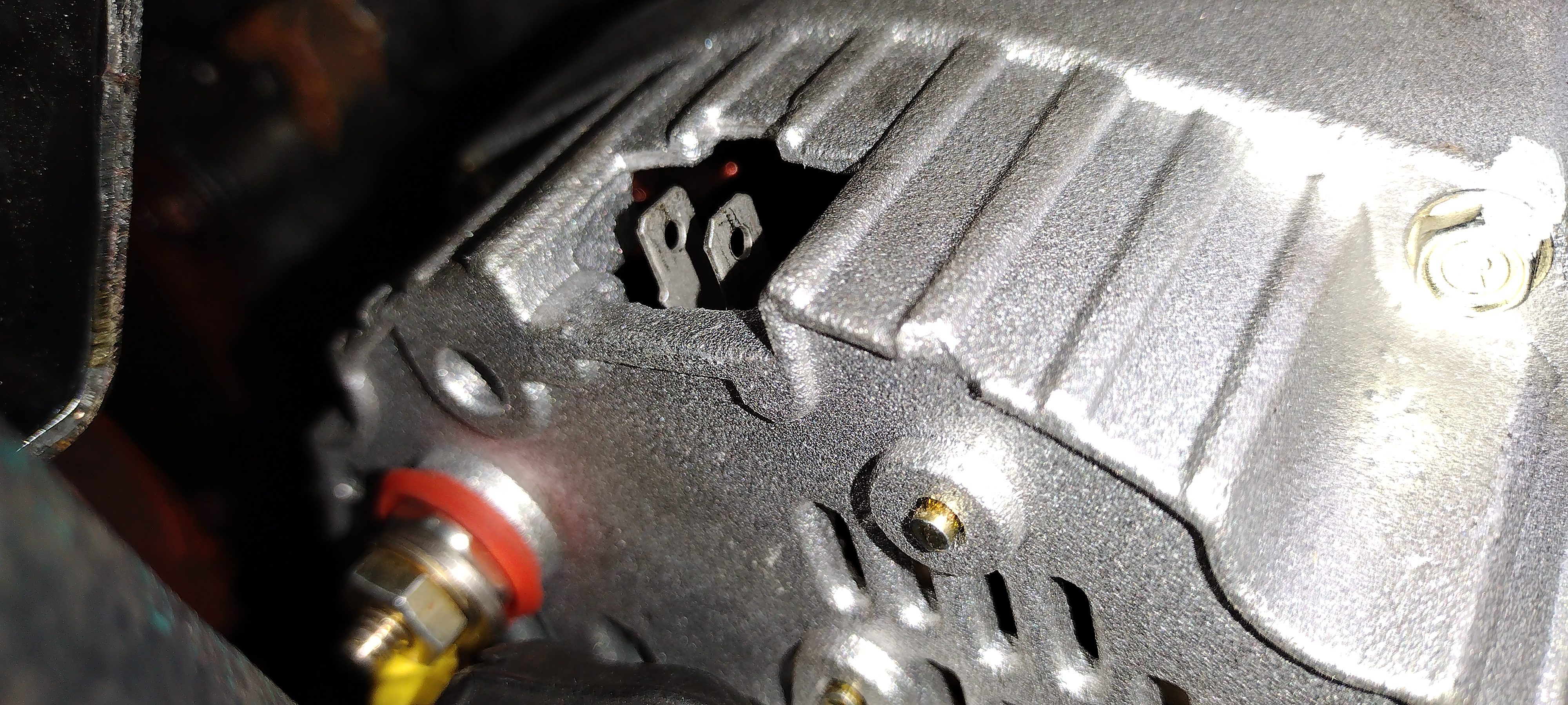
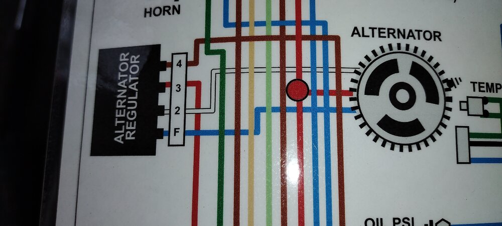
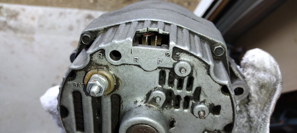
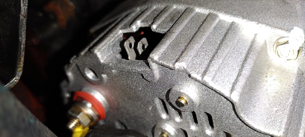
Ah man ... classic error. I had the wires swapped on the 2-pin connector. I would have bet a paycheck that the 1 position was the F (Field) wire. I just cleaned up all of the gunk off my old alternator to reinstall it. Once all the gunk was gone I could CLEARLY see that Pin 1 is R (Reference 12V) and pin 2 is the F. Can't believe how much time I spent not believing I had it backwards!!! The new alternator doesn't have any markings on it. So it's a guess. Thank goodness I saw the markings on the old alternator and put 2 and 2 together. The wiring diagram I bought is correct. It's just that the pin numbering on the voltage regulator does not correlate with the pin numbering on the alternator. I wonder if it is supposed to (?). So, the alternator saga has now come to a close. I'm getting >14v on the battery right now when the car is running, and the GEN light goes off once it starts. All is well with the world of my 72 Monte now. Time to go enjoy driving it for a while before I take on anything major. Have fun everyone.
-
Yeah, I'm going to be pretty embarrassed if I burnt up a 2nd new alternator. The current new alternator I had bench tested when I picked it up and it checked good. Whereas the 1st one tested bad. But yeah, a bench test will prove or disprove. Dang it!!
-
@Scott S., the battery is nearly brand new. I replaced it a few months ago and have barely put any miles on the car. The voltage regulator is brand new, and I confirmed continuity from its terminals back to the alternator 2-pin connector. Yeah agreed, something is preventing the alternator from charging. The regulator is definitely signaling to the alternator to start charging. It just isn't. The battery will of course hold a charge until it doesn't. The voltage will eventually creep down and then not allow the HEI to operate, or the starter for that matter
-
Update: ALTERNATOR IS STILL NOT CHARGING!!!!!! Man, what a pain in the butt. - I threw in the new (replacement) alternator and new voltage regulator. - I connected in the new 2-pin connector and plugged it into the alternator - I pulled the starter back out, fixed the melted wire loom (forgot to tie it back from the header), confirmed the 10 gauge wire back to the alternator is intact, and reinstalled the starter - I now get 11.6v to Pin 1 (exciter wire) on the 2-pin alternator connector vs 9v previously - With the key forward the Gen light is now much brighter ((11.6v vs 9v likely) - The Gen light on the dash does not go off when I start the engine, indicating it's not charging - The battery is down to just over 12v whether the engine is running or not. Could I have killed another brand new alternator somehow? And how would I have killed the first alternator? I'm definitely not understanding something
-
Update on the alternator - I ended up pulling the brand new alternator out, bringing it back to OReillys for a bench-test, and determined that it was a faulty unit right out of the box. In all my years I've never had that happen on starters, alternators, etc I dont think. But there it is! I will be picking up the new alternator, as well as a new voltage regulator from the parts-cannon, this afternoon. And I have a new 2-pin connector coming from a vendor on Amazon as well. So fingers crossed my minor alternator saga will be figured out. Note that the old alternator was charging just fine. But when I took the nut off of the + post on the back of it the post started to turn - someone had used a lock-nut on that post ... ugh!!!! I suppose I could have opened up the alternator and tried to fix the post, but there was so many years of built up crud on it and in it that it didnt seem worth the time. Worst case scenario though, I could try a DIY rebuild and put it back on - no plan to do so though. I'm hoping this ends this thread for now and I can continue driving my MC for the summer. I suppose I should tackle the dash lights not coming on too ... hmmm. We shall see
-
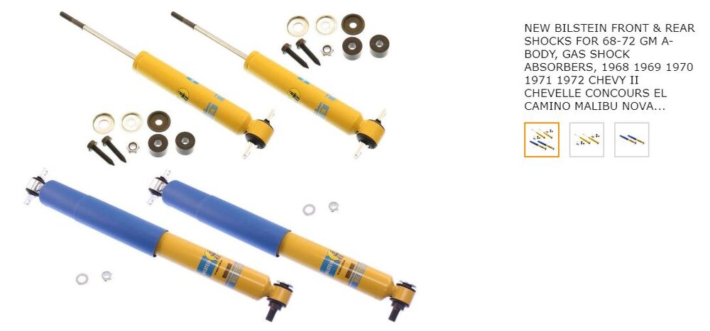
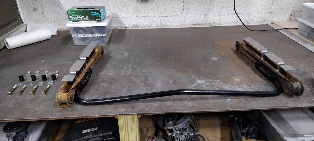
Update: my MC now handles REALLY well!!! Man, what a difference the boxed rear lower control arms, sway bar and Bilstein shocks make!!! Wow ... just ...wow!!! I went for a 20 minute drive through some of the Connecticut country back roads in my area. The 'curvy road ahead' signs quickly became my favorite sign :). The body roll seems near zero comparatively. And the ride is still very comfortable. I've still got some wiring issues associated with the alternator to figure out before I can daily my MC again. But I will get those sorted out quickly I'm sure.
-
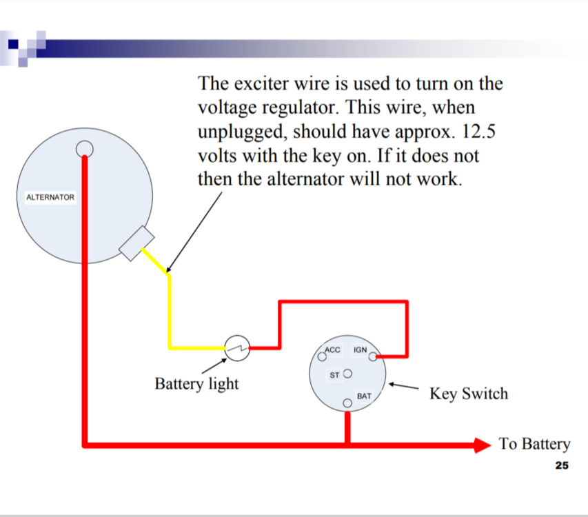
I got the new mini high torque starter installed and all of the wiring squared away. It started up on the first try. Yay!! All is well ... Except ... the new alternator is not charging. Dang it!! This is just a standard alternator I picked up at OReillys since the old one is so gunked up and the positive post spun on me as I tried to take the nut off (unit now questionable). I have to think that it's good since it's new. But I guess one never knows. When I kick the key forward the alternator light comes on dimly lit and I'm only getting about 9vdc at the igniter wire. Should be 12vdc or whatever the battery is reading I believe. So there is some significant resistance somewhere. As I understand it, if the igniter wire doesn't get 12 volts, it doesn't kick the internal voltage regulator on. True? So I have some troubleshooting to do before I bring the alternator back. The 2 wires to the alternator are pretty stiff and old. I should have reran new ones before I loomed everything. I will unloom it all and trace those wires back, next step.
-
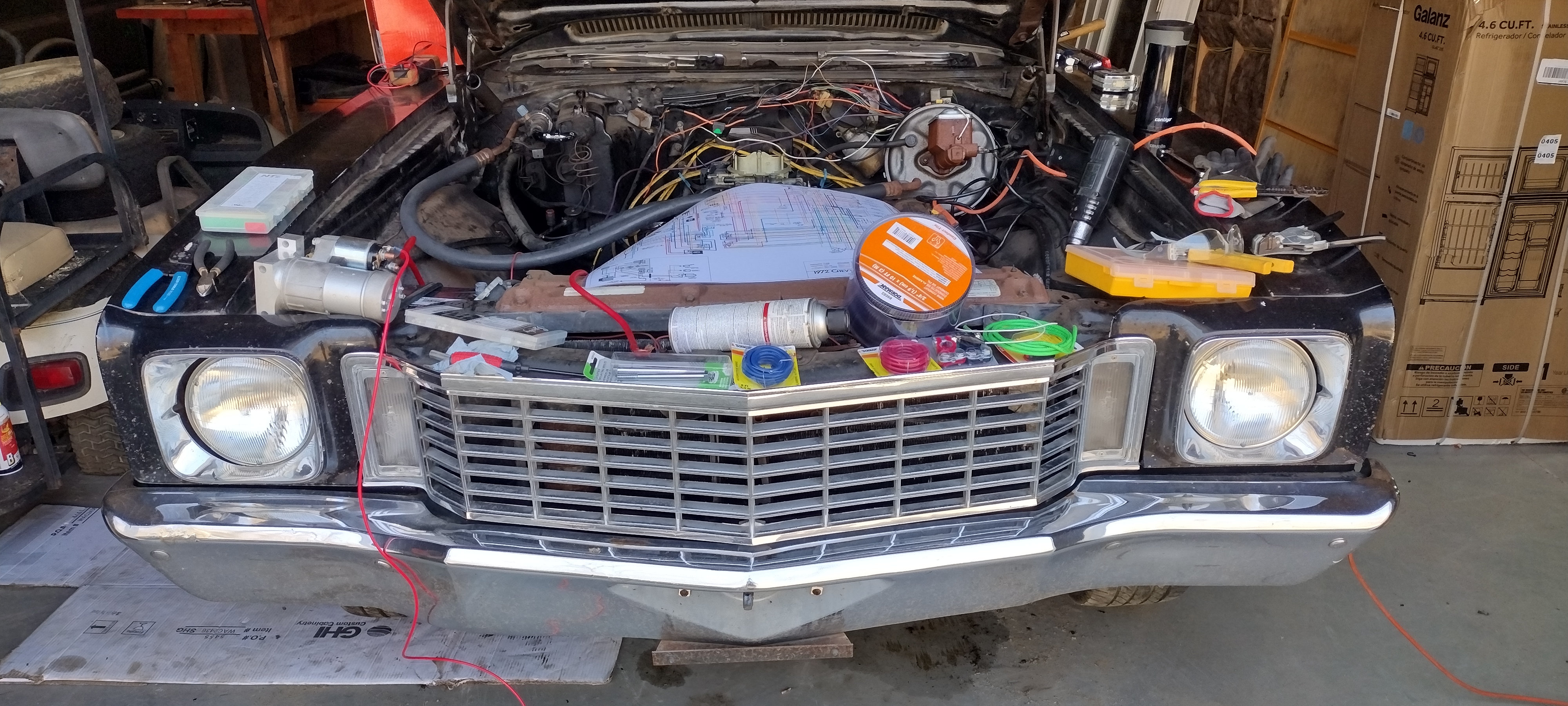
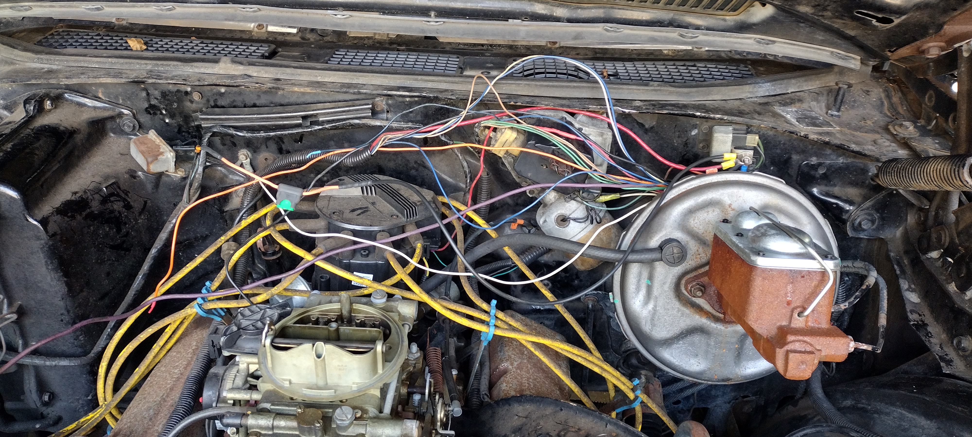
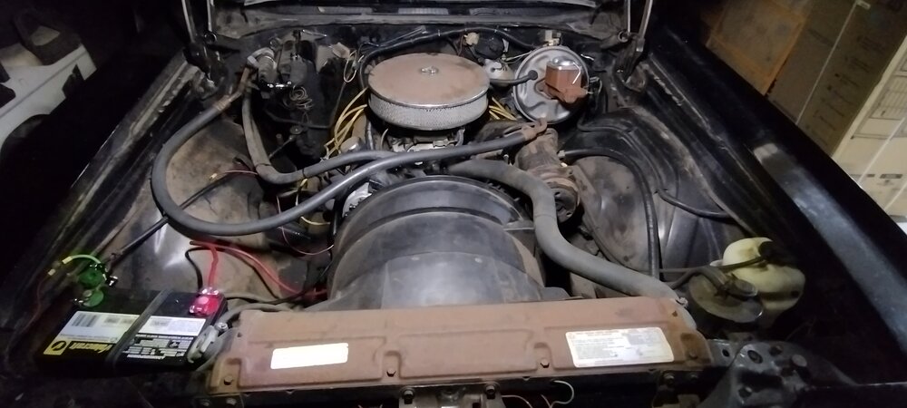
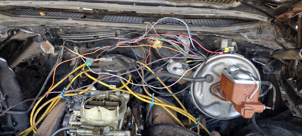
A reminder ... this all started due to a broken starter. And here I am redoing A BUNCH of wiring! The big, laminated wiring diagram linked above is awesome. Totally worth the $35 or whatever. I will probably end up hanging it on the wall - sort of an art piece to be honest. Above the brake booster is the Horn Relay. There are a number of 12V heavy gauge wires that come in to that point, including the direct line from the battery / starter / alternator. Almost all of these wires, at multiple points, were burned through. It's really incredible the car never burned to the ground. While a full harness replacement is probably in the future, for now I'm just pulling back all of the electrical tape and loom and checking / fixing every wire and connector. Hopefully I will get enough of the wiring repaired to get the starter back in this afternoon. We shall see!

-
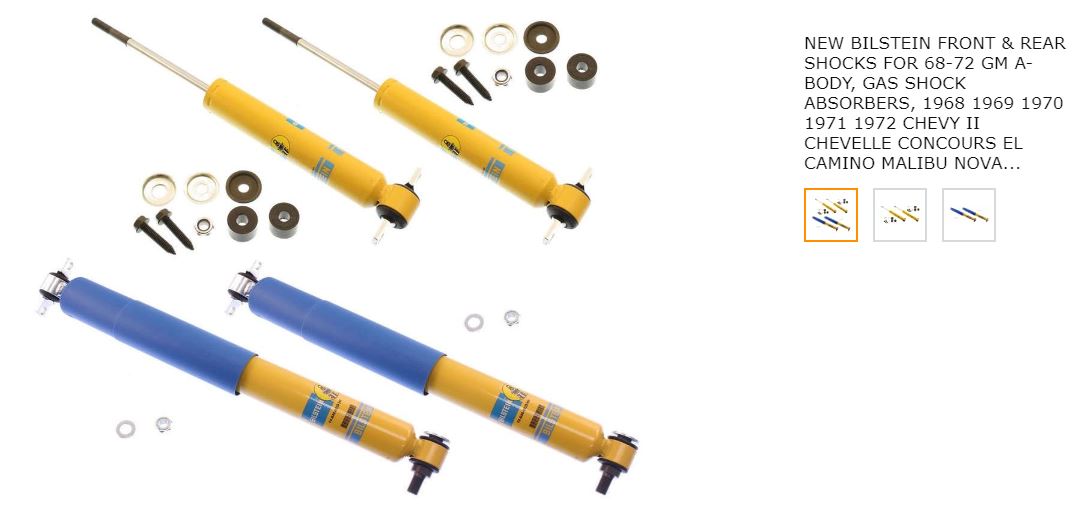
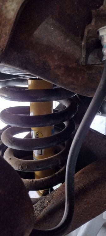
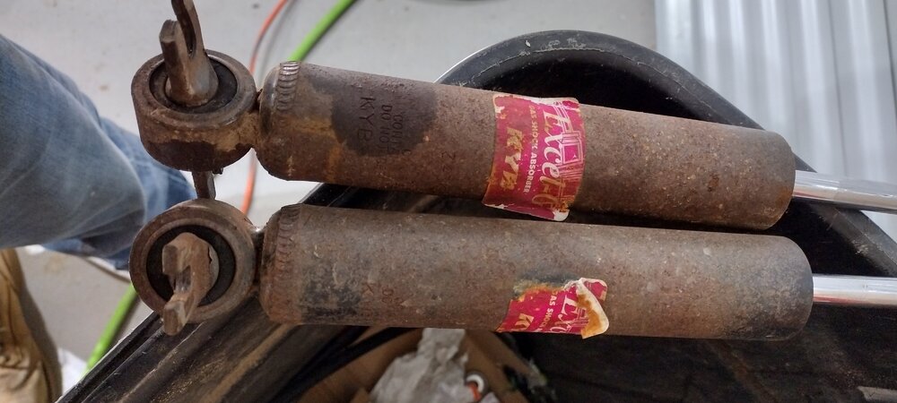
I got the front Bilsteins in without too much of an issue. I had to run down to the auto parts store to grab some new, short 5/16-18 clip nuts for the lower shock bolts. Plan on replacing those while you're at it. Sort of a shame Bilstein doesn't include those to be honest. The old KYB shocks I replaced seem to have some good damping action. But they look like heck! Still glad I replaced them, along with the rears. Only time will tell if the Bilsteins are worth the 3x price tag. Other then some new BF Goodrich Radial TAs per the earlier posts on this thread, that's all for the suspension for now On to the continuing saga of the starter replacement (other thread)!!!
-
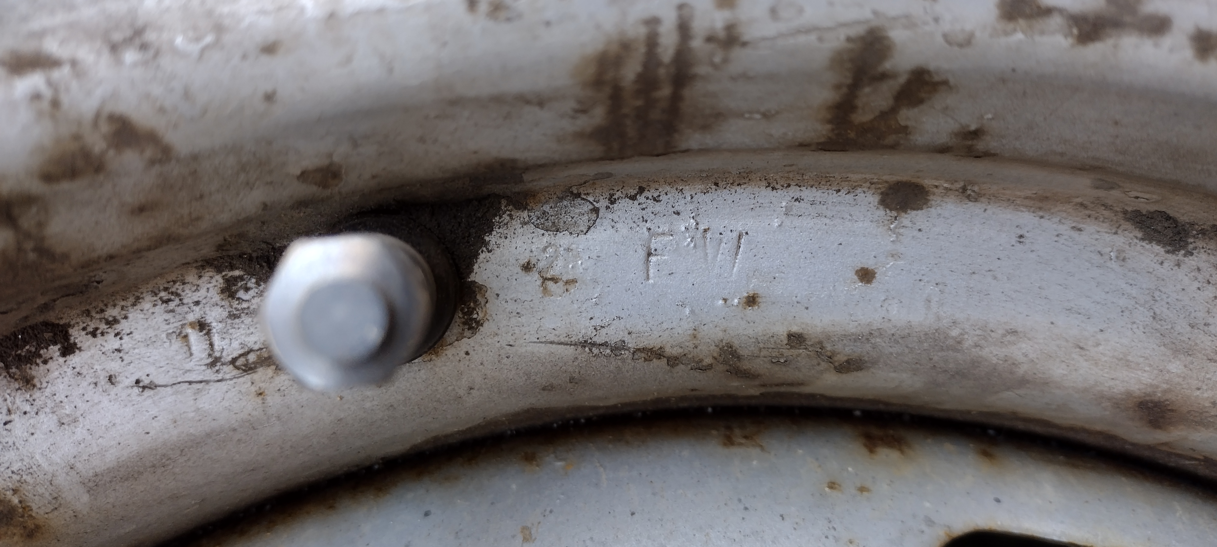
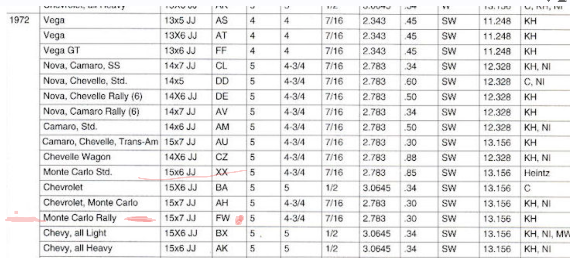
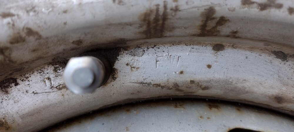
@jft69zand @Blackhawk, I finally finished the rear shocks and was able to turn my attention back to the wheel code / size. I found the FW marking stamp just to the right of the valve stem. For my 72, this means that they are indeed 15x7 Monte Carlo Rally wheels!! Yay.

-
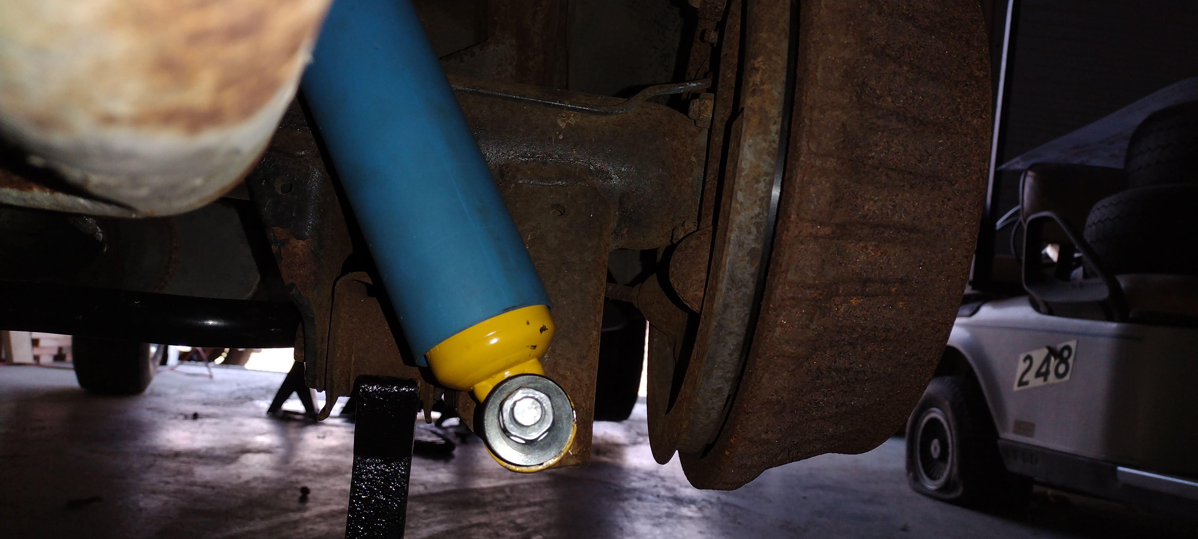
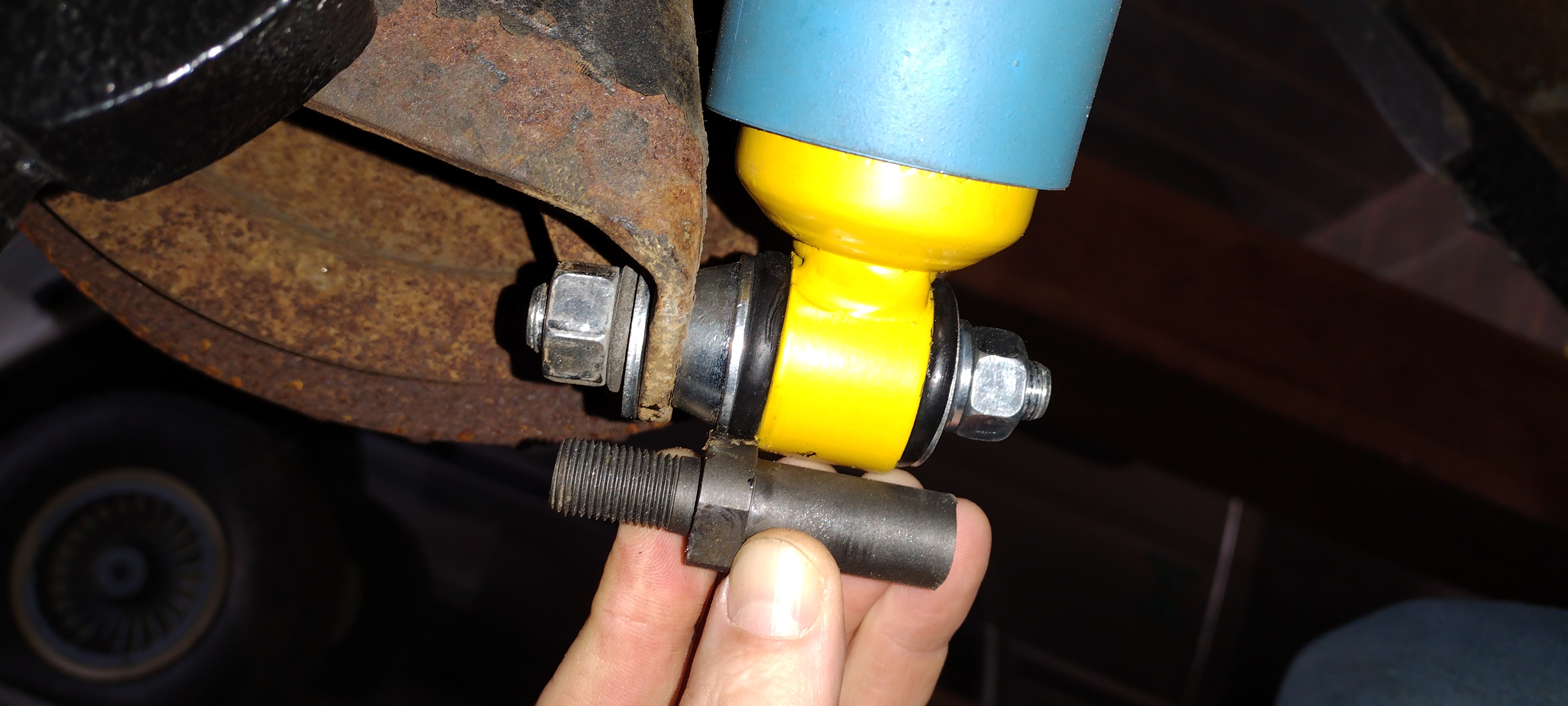
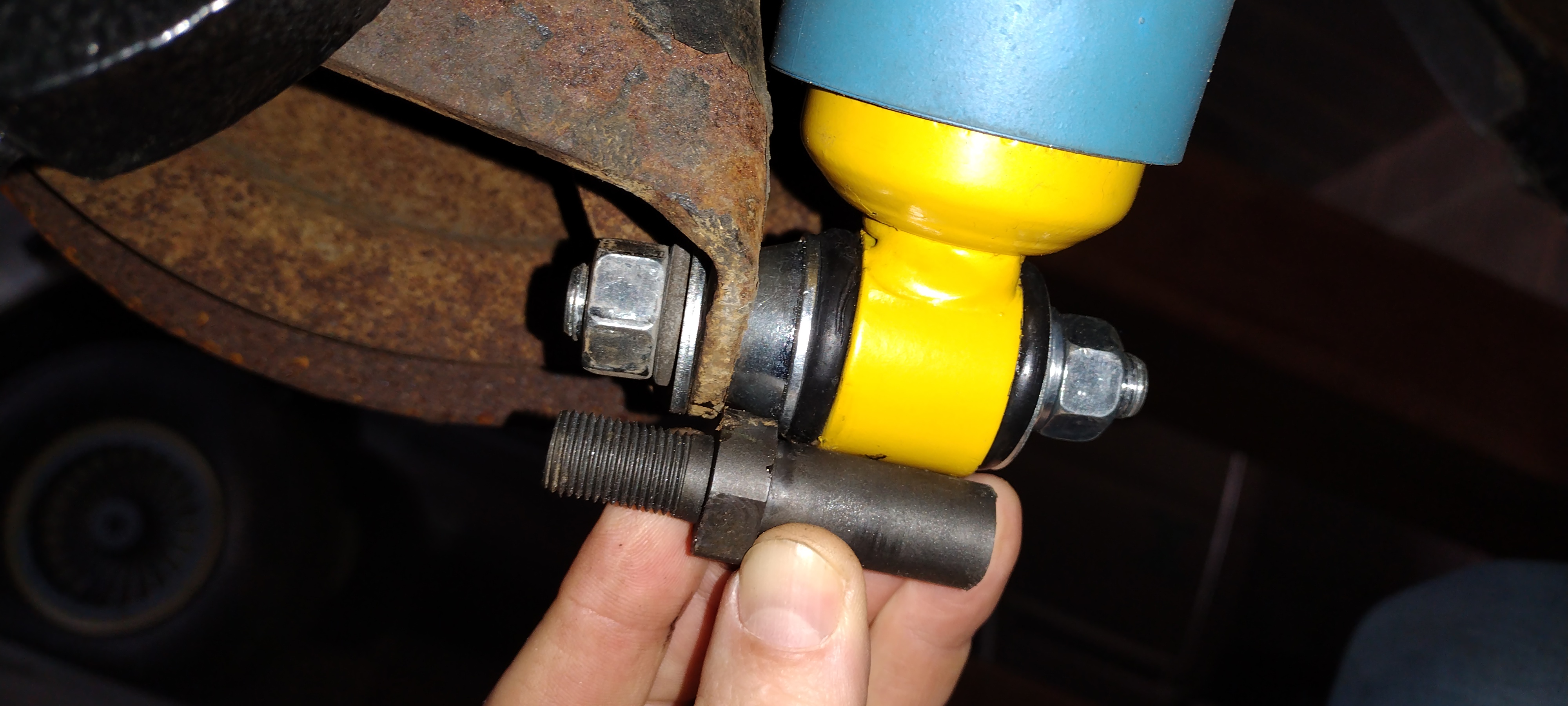
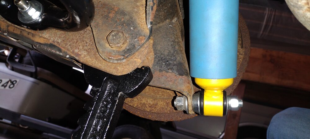
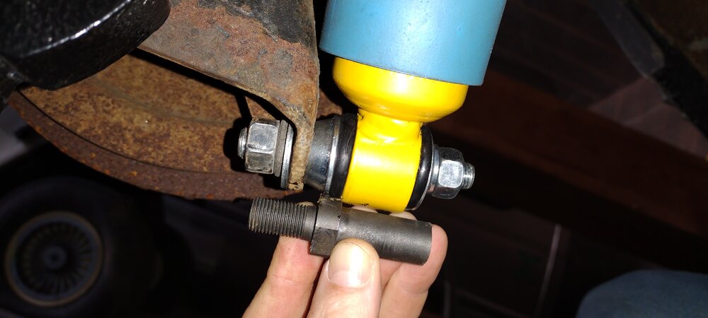
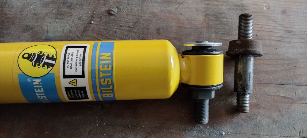
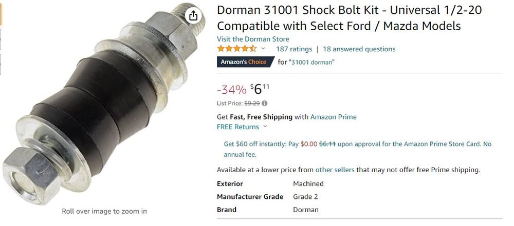
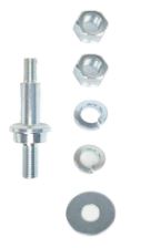
FINALLY got the Bilstein shocks installed. Yay!!! Unbelievable how many hours I have in to what should be a simple job Bottom line - if you buy Bilstein shocks for the rear of your Monte Carlo, be sure you buy the Dorman (or similar) bushing / stud / bolt assemblies. You will have to cut out the bolt / stud that comes with the Bilstein shocks, remove it and the bushing, then install the Dorman assembly, all prior to installing the shocks in your car. Attached is a picture of the final result, as well as 2 pictures showing why the bolt / stud that comes with the Bilstein shocks doesn't work. If you don't see it, just move on - definitely not worth taking up more room on this server with more discussion


-
@MC1of80, those pictures also highlight the problem with the Bilsteins. They don't provide enough of a spacer to prevent the tube from contacting the mounting bracket, and then the stud isn't long enough to (a) go through the mounting bracket and (b) accommodate a nut and a washer. Again, this would all be solved if I could have pressed the Bilstein-provided bushing onto the stud / bolt I removed from my old shocks using my bench vise. I proper press or bench arbor might have allowed me to be successful. Hopefully this will all be solved with the Dorman bolt / stud / bushing assemblies @jft69z, yeah I havent researched the alternative Bilstein part numbers yet. Nor have I actually tried to call them, which is probably the needed approach. I'm focused on solving the problem by other means, hah!
-
@jft69z, there isnt enough threaded stud length, trust me. If there was, we wouldn't be having this conversation! I would have to think that maybe Bilstein sells a different rear shock part number for the first generation Monte Carlos, and that part has a similar bolt / stud as standard shocks for this model. Again, I can buy a cheap pair of shocks for about $30 and get the parts I'm looking for. I just figured I'd try solving it for $12 with the Dorman parts, with a 2-piece bushing, first @cny first gen 71, yeah I did those laying on the floor. It was actually quite easy - coming out and going back in. Just read the tips in my previous post - cargo straps, etc.
-
@MC1of80 and @cny first gen 71 , adding a spacer in would then eat up the length of the available threaded stud. You can see the 'spacer' that's on the stub / bolt that I removed from the old shock and tried to install on the Bilstein. That spacer, plus the thickness of the mounting bracket and a washer wouldnt leave very many threads for the nut. Call me crazy, but I like my bolts to go through the but completely with a few threads showing! So ... no, you cant just add a spacer, bolt it up and go about your merry way. Trust me, I tried to convince myself of that as I was laying on my carboard creeper under the rear of the car. I've got those Dorman hack assemblies on order. And they might be good enough. If I can find good, replacement, 1-piece lower rear shock bushings by themselves I will grab them and then use a proper press and fixtures to insert the stud / bolt into them and into the shocks. But for now I will go with the Dorman parts when they come in. I will post some pictures once I have them installed. Thanks again for the input
-
Gents - here is a clearer picture of the issue. The Bilstein shock bolt/stud isn't double-ended. It's just got a flat washer flared onto the end. If I try and put the threaded stud portion of it through the mounting plate, the tubing of the shock hits the plate. That's why I pulled that bolt out and tried to install the ones from my current shocks. Hopefully the Dorman parts work. What a bummer though
-
I just ordered some cheap Dorman rear shock bolts/studs and bushing sets. They're probably going to be a little bit of a hack, but we'll see. If anyone knows where to get some high quality ones, and new Bilstein-quality (?) bushings, please let me know!
-
Well guys, I'm glad I had a great day yesterday boxing in the rear lower control arms and installing the sway bar. Because today was an absolutely HORRIBLE day installing the Bilstein shocks, or trying to anyway. So horrible. In fact, I've just plain given up after having only sort of installed one of the rear shocks. I have more time invested trying to get the rear shocks installed than I put in on the lower control arms and sway bar yesterday. No kidding! First ... the upper bolts for the rear shocks are nutted on the back side, against the bottom of the trunk floor. There is zero visual access to the nuts and very little finger / hand / tool access. Who does that? My god, what an absolutely stupid setup. There's plenty of metal there, and I'm not sure why they wouldnt have just threaded it through the thickness or had floating nut plates or something ... anything but a blind nut. So, that took a while to figure out the right acces and set of tools to use. Then ... when installing the rear BIlsteins P/N 24-009294 I realized that the hardware through the bottom bushing was not going to mount to the mounting plate on the axle. It didnt have a standoff on it. Dang it! Wrong part or is this just the way they do it? I ended up cutting the riveted washer off of the studs, then pulled them out of the bushing. I then went to press the old / current studs into the bushing and a nightmare ensued. I only have an old bench vise and a selection of sockets to make this happen. I ran to the local harbor freight to grab a bench top arbor press, but no dice ... out of stock. I spent hours trying to get the new Bilstein bushings pressed onto the old stud and into the shock. I got one done but ended up sort of stripping the threads on the stud accidentally. The shock is installed in the car, but I'm not happy at al with that lower bushing and stud. I tried for quite some time to get the second stud / bushing / shock together and finally had to throw it down in disgust and walk away. So now I'm in the market for new studs and bushings. I may end up buying a cheap set of shocks just to get the studs and bushings since I dont seem to be able to get them separately. Once I figure that out I will just bring all of the parts into work and use the hydraulic press there to get it all together - hopefully! So, today was a really unfortunate fail. I could NEVER have imagined rear shock, or fronts that matter, to be so unbelievably difficult to install. I cant believe it. I'm beside myself with frustration. Ugh! More later ...

-
I was going to do the same thing. I had the sway bar in my cart on Summit. Then of course the site 'recommends' the inserts for $32 or whatever. I bought them figuring I would install them with the sway bar and then weld later while installed. But the solid bushings that come with the sway bar - to brace across the inside of the arms - wouldn't fit with the inserts in there. So, here I am having done the job properly. Who would have guessed, haha! Honestly, the whole thing was incredibly easy to do. A good, fun project for the day. Enjoy the rest of the weekend everyone!
-
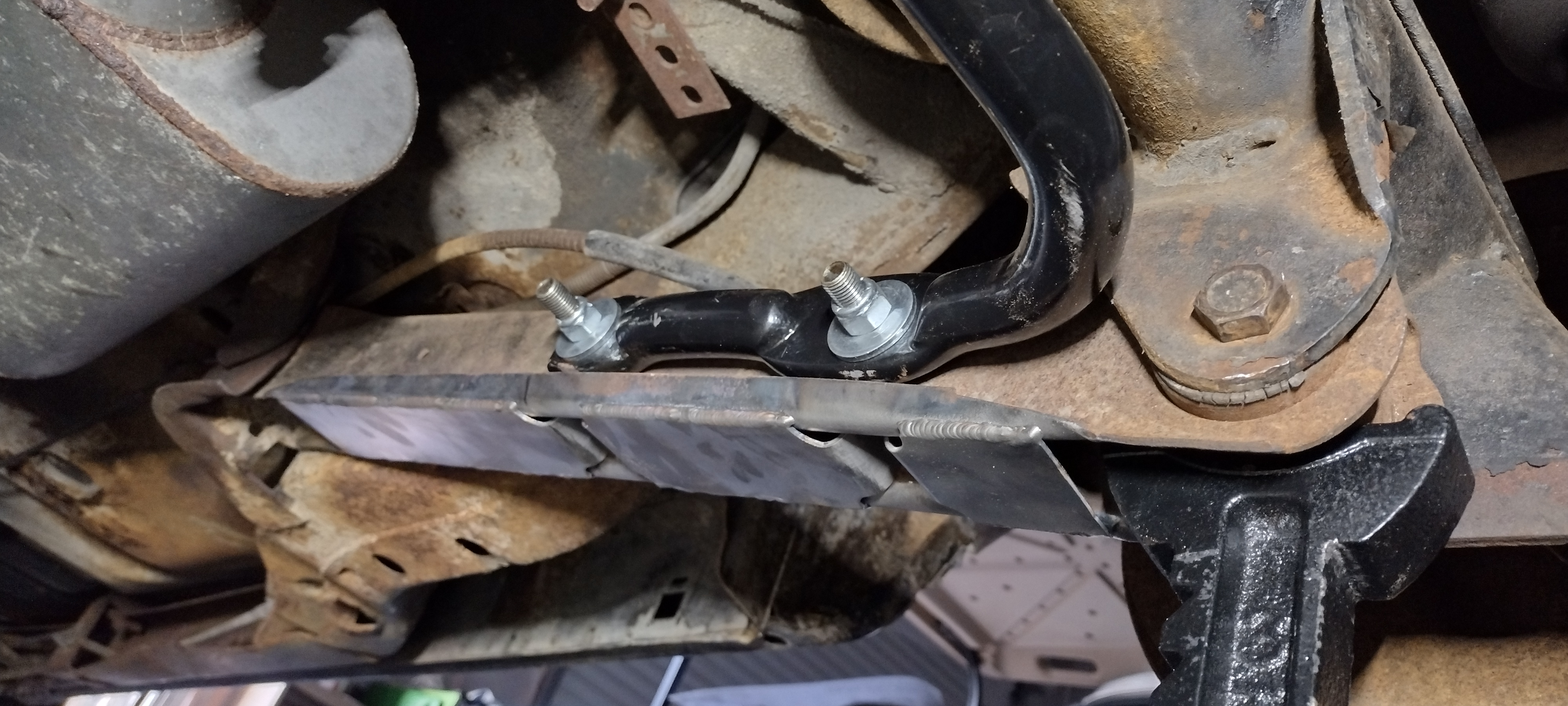
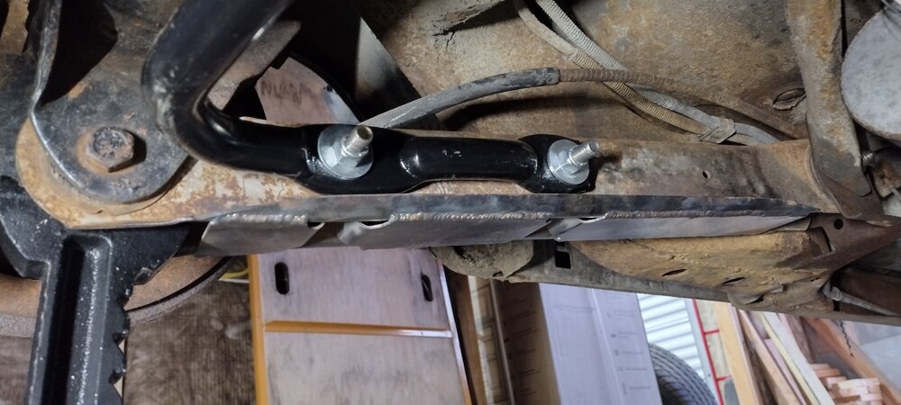
Success - boxed lower control arms and a sway bar installed! Today was a good day for sure. Everything went right. I will have to tuck this one away for all those days that go to crap. During installation of the control arms I found I had to use a heavy duty cargo strap to pull the rear end forward a bit in order to get the AFT bolt to line up. I installed the FWD bolt first. I put the cargo strap between a drain hole in the frame under the door, then back to a wheel stud sticking out of the brake drum. I also found that installation of the sway bar means I lose the ability to put jack stands under the rear end - bummer. I also now have limited access to the rear end pumpkin to use as a central rear jacking point - bummer. I had to put a 2nd set of jack stands under the AFT control arm bushings in order to move the 1st set out of the way for the sway bar to be installed. Lucky I have 6 jack stands for whatever reason! I'm done for the day. Tomorrow I will get the Bilsteins installed as long as wifey lets me spend another day in the garage. She's a keeper and so I want to keep her And after the Bilsteins I'm done with the suspension for now, other than tires. Oh, and a Jeep steering box I guess. I will move on to the starter replacement (other thread) and the previous owner wiring mayhem I've uncovered - ugh!! I will get it done though. Easy peasy. Thanks for all of the help so far everyone. I really appreciate all of the info and guidance. Such a great group!!!

-
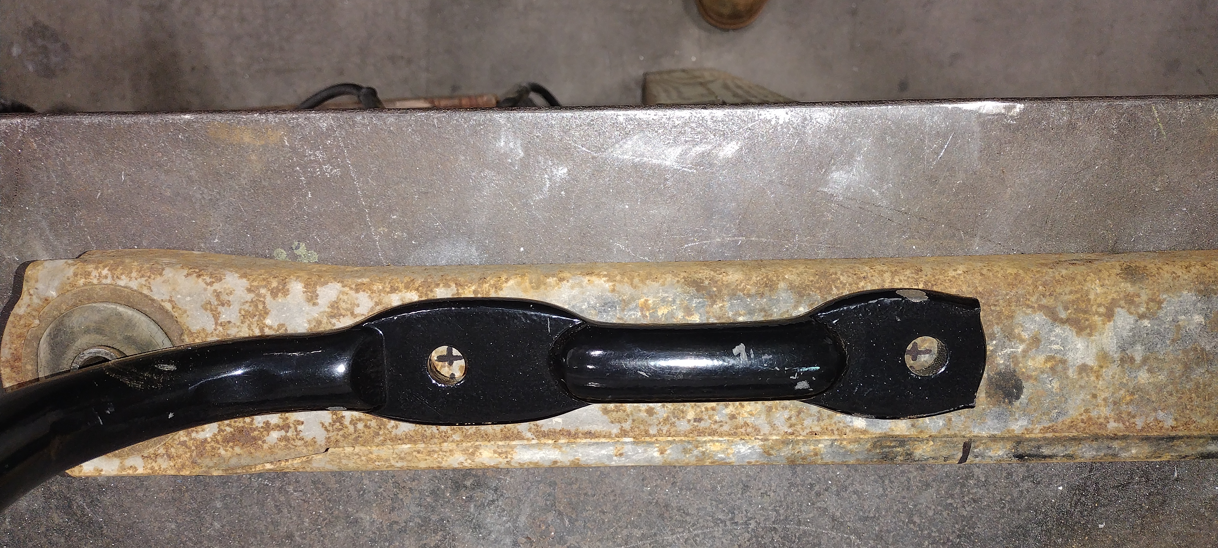
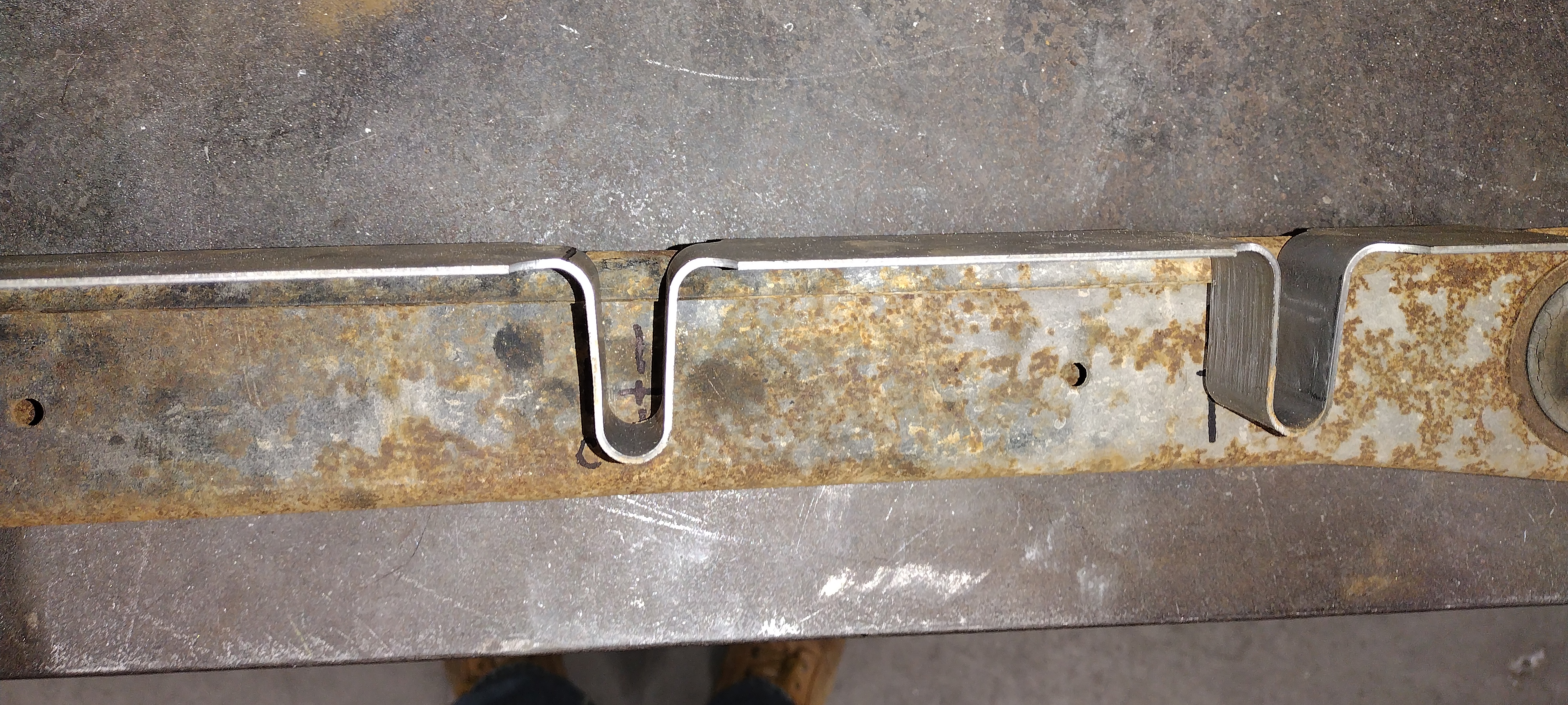
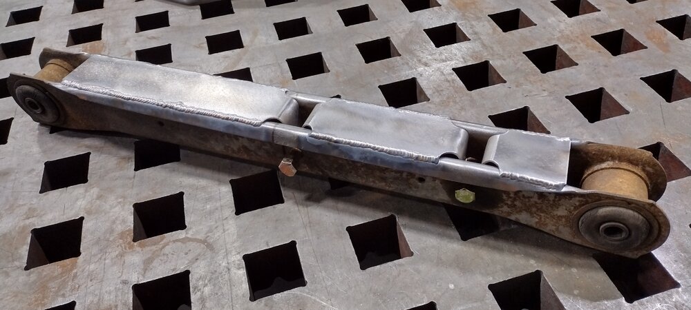
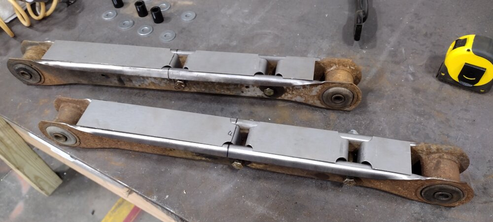
So here is what the rear lower control arms look like after welding. Pretty cool! I kind of enjoy the 'patina' so I'm going to leave the metal uncoated - our media blaster is awaiting replacement or I would have cleaned them up and painted them black. Maybe later I should be able to get these control arms and the new sway bar reinstalled this afternoon. So all in all this was a pretty quick and easy morning / afternoon project. Oh, and my new Bilstein shocks came in too!!! More on that later
-
@jft69z, thank you for that link. It's pretty helpful. I also came across that this morning during Googling! I agree that the top hole should indicate FWD. That's the way I went anyway. It does seem like the arms are symmetric but I wouldn't bet a paycheck on it. I couldn't find a template anywhere on the Internet. So I had to make some measurements and guesses and go for it The sway bar mounting holes measure 6in apart on each side of the sway bar. And the inserts, although just imprecisely bent sheet metal, are pretty consistent and also measure 6in arc to arc. The rear lower control arms measure just shy of 25in long tip to tip. So I measured to the 12.5in mark from the FWD end and called that the centerline. I then set the FWD sway bar hole 0.5in AFT of centerline, then the AFT sway bar hole 6in AFT of the FWD one. I eyeballed a good height location for the sway bar and ended up converging on a hole center that is 15/16in down from the edge of the curled lip on the sides of the control arm. I'd go 7/8in if I did it over again. I drilled 1/2in holes in the measured locations. And then I set the boxing inserts down in with a hammer. The holes lined up really well. But as I mention above, reducing the vertical distance of the holes to 7/8 would get a more free fit with the inserts in. It works though! The control arms are currently on the weld bench waiting to get zapped in place. This was WAY easier than I had anticipated. Though I'm leveraging the metal shop at my work, and buying the welder a 12 pack of his favorite beer At some point when I do a full suspension upgrade I will donate these boxes control arms to a good cause and go with the solid billet ones - me likey likey!

-
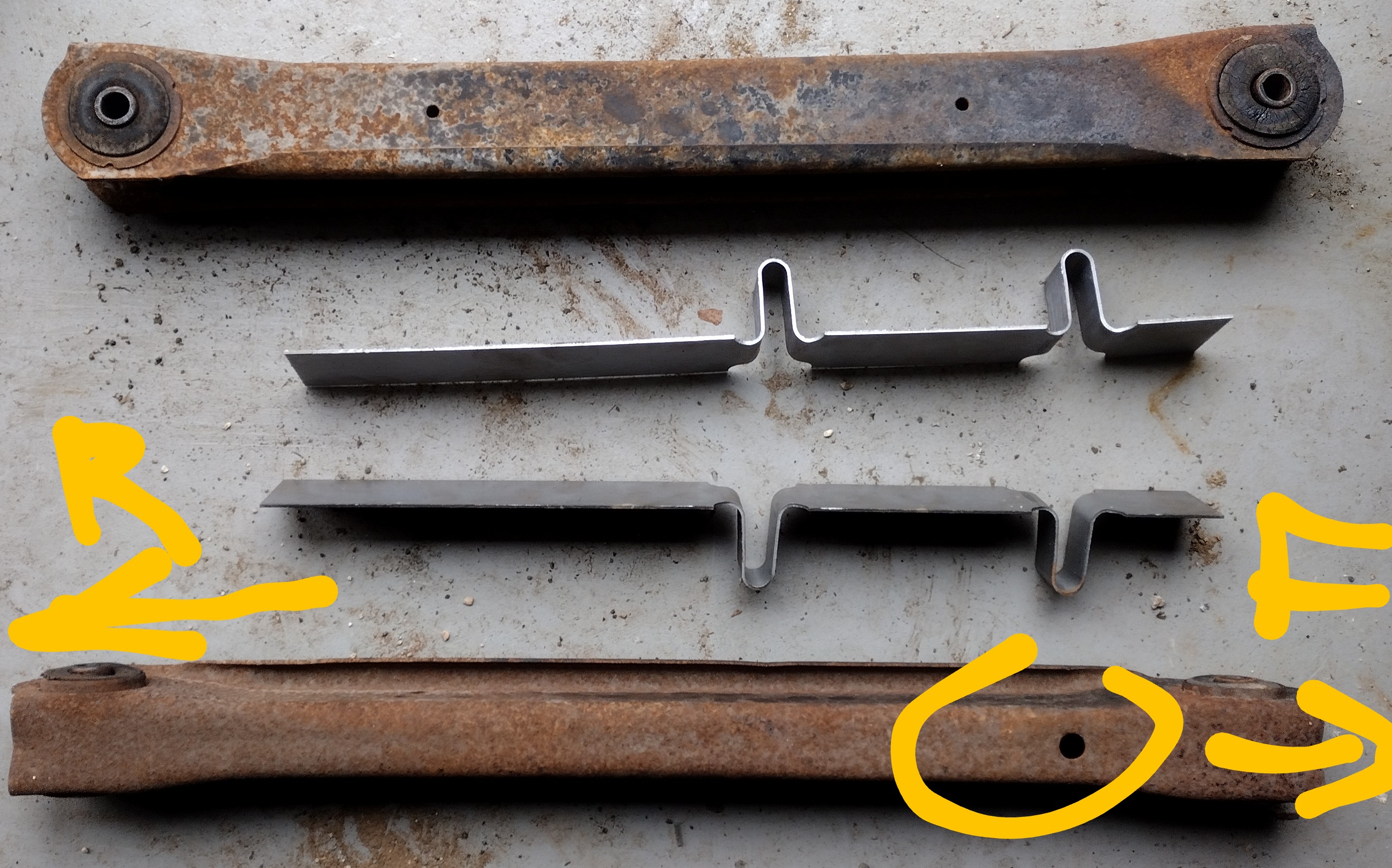
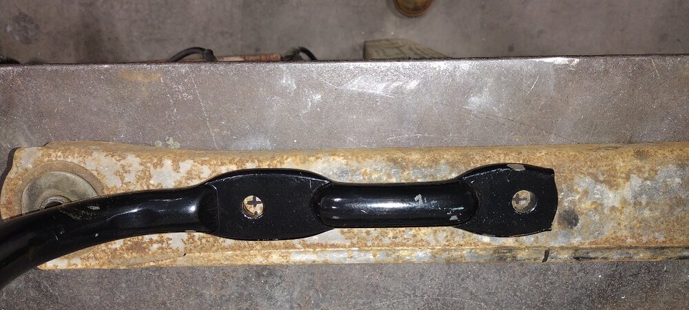
@Blackhawk, sorry about the above post. It's a misfire / issue with the editor. I can't seem to delete it -------------------------- REAR LOWER CONTROL ARMS BOXING - I've got the rear lower control arms off, and I have the boxing inserts ready to weld in. But ... I didn't note FWD and AFT on the control arms when I took them out. Yikes!! Is the hole in the top (circled in yellow) supposed to be FWD? What orientation to the inserts go? As shown or other way?

-
@Blackhawk, ok near the valve stem. I will check that out and post a pic tonight when I get home. That should be the final piece to me then confirming some numbers / fits / clearances and then getting some tires ordered @Rob Peters, awesome, thanks for the update. I will start poking around further and will update my profile, etc.
-
@Blackhawk @MCfan and @jft69z, you guys are a HUGE help! Thanks so much for all this, and no doubt its a repeat of stuff already on this forum. But I appreciate you regurgitating it so that I can figure out just the right tires and not waste $800! @Blackhawk, you've absolutely pointed out an error in my above stated rim width measurement of 15 x 8. I was eyeballing lip to lip, sort of through the tire since the current tires are all still mounted. I eyeballed 8in lip to lip which means I probably have 15 x 7. Once I get the tires dismounted I will take some actual measurements for sure. And what do you mean by "the barrel" so that I can look for the code and compare it against the list that @jft69z posted and linked above? Do you have an example photo of where that code is found? @MCfan stated to Joe that "Your front 15x7 rims with 4.25 bs (+ 6 mm offset) are almost ideal for a first gen Monte as the factory rallys are very close at +8 mm offset)." I 'm nearly 100% convinced that I have these "almost ideal" wheels on my MC :). I'm sure I measured the backspacing correctly at 4.25in. And in other news, my new rear sway bar came in!! As well as my new high-torque starter (other thread). I'm still waiting for the lower control arm boxing inserts and my new set of Bilstein shocks to come in. Note that my plan at the moment is to 'loosely' install the boxing inserts into my lower control arms, and use the tube / standoffs that came with the sway bar. In the next couple of weeks I will be over at my buddy's house who has a welder and a shop, so we should be able to weld the inserts with the lower control arms installed (fingers crossed) - it's just a mild hack until I upgrade my suspension completely with billet or properly boxed lower control arms Thanks again everyone. Super helpful community here. Hopefully @Rob Peters cashes my check soon and updates my account so I can be even more active!!!
-
@MCfan, holy cow ... wow, that is some really great fact finding!!! Thank you so much for taking the time to do that, and to type it all out here. Many others will benefit from that exercise down the line. I will check out the tire size calculator - I've used that one before, very cool - and will check your numbers. I will also get the current wheels / tires back on and drop the jack stands so that I can check the current clearance against what you've calculated. Note that I'm pretty sure the rally wheels are 8in wide. Hard to measure directly with the current tires on there of course. I will eyeball it again or come up with a better indirect measurement method, but I highly doubt they are 7in wide. That will make a difference in the calculations of course. Thanks again. Super cool of you to do all that!