Paul Bell
-
Posts
893 -
Joined
-
Last visited
-
Days Won
43
Content Type
Profiles
Articles
Forums
Gallery
Events
Everything posted by Paul Bell
-
TCS relay stuff or idle speed solenoid.
-
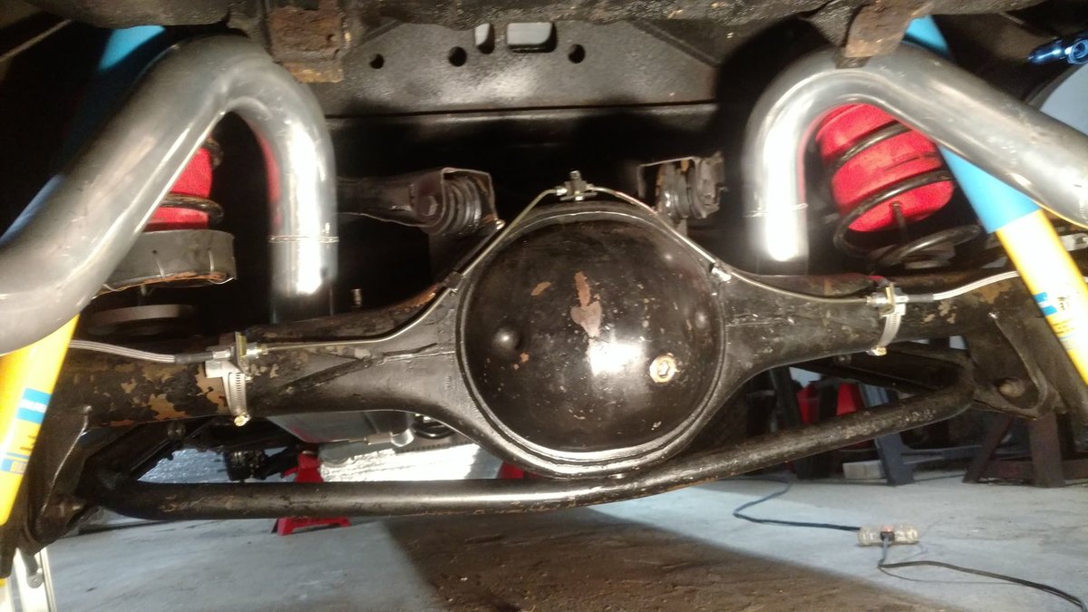
The lines from the master cylinder to the proportioning valve should be 1/4". From the proportioning valve to the rear T-block on the rear, the line is 1/4". From the proportioning valve to each front wheel is 3/16". 1970 cars will have a hold off valve under the brake booster. I re-did all my lines with 3/16" stainless and I used a Wilwood adjustable valve that mounts on the master cylinder ports. It's outlet port to the rear is 3/16" so that's what I ran back.
-
What did you do to your Monte Carlo today?
Paul Bell replied to Canuck's topic in General 70-72 Monte Carlo Forum
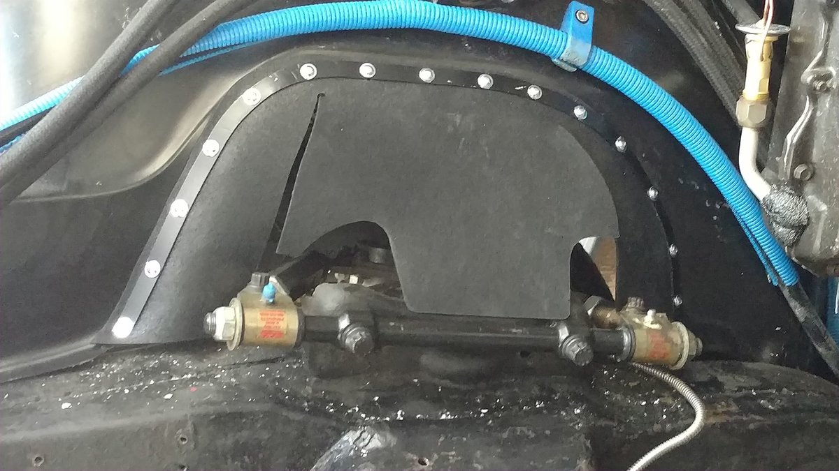
I decided to redo how I attached the fender skirt water flaps. Stainless wire stitching wasn't doing it for me. I shaped some 1/2" x 1/8" aluminum flat from Home Depot to match the outline of the attachment point. Then used allen button flange head screws and flange nylock nuts to secure it all.

-
That's really the best thing to do with these cars, if you can afford it and it's not a dead stock show car. This is a mod that can be undone so it doesn't impact the car's value. The Digital Dakota system is pretty amazing. It not only brings modern instrumentation to our cars, the options are almost endless. You can set alarms for just about any out of range reading, volt, oil, water, etc. They offer inline current monitoring that can monitor anything-like let's say an electric water pump. If it blows the fuse the displayed amps go to zero. GPS for speedo, vacuum, exhaust AFR, tire pressure, etc.
-
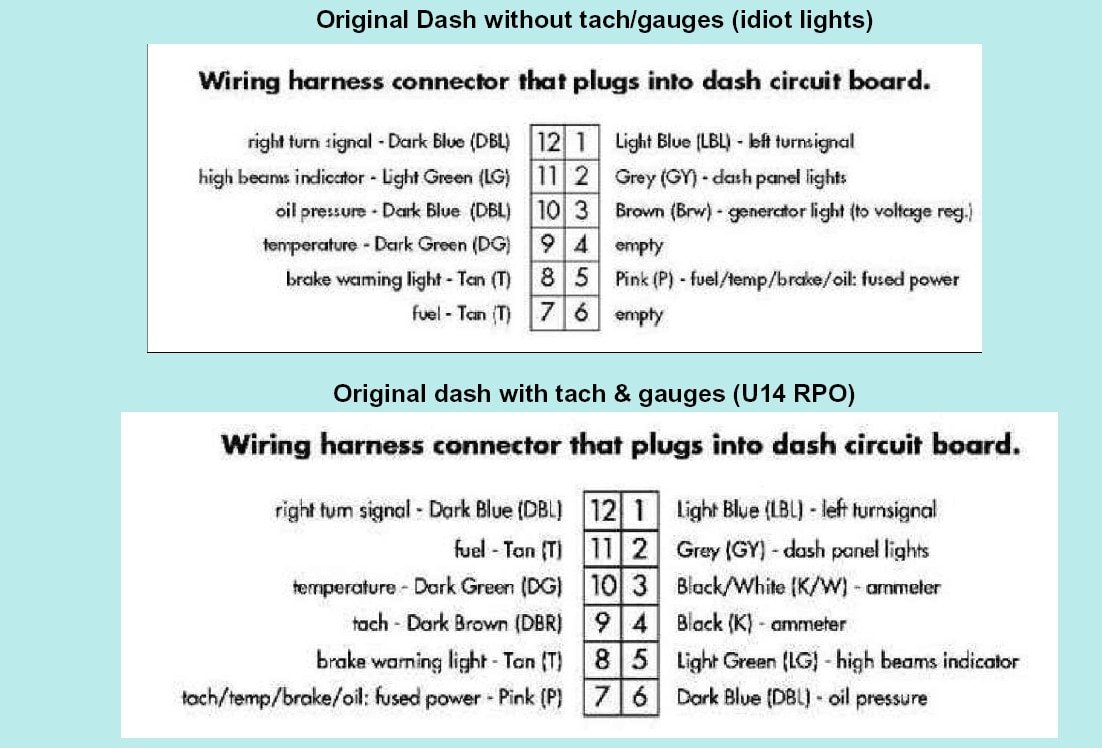
David, I haven't done this mod but it looks pretty simple. Cut in the harness the contact 3 wire (black/white) and splice it to the pink wire (this becomes hot when the key is on). Cut in the harness the contact 4 wire (black) and ground it somewhere. After doing this, make sure the + terminal on the new volt meter goes to the spot on the flex circuit board that reads power when the key is on.
-
A few wires needed to be moved to other plug locations. Here it is:

-
Yessir, that sounds very plausible. I can't view the the thread now. Does it say where to put the diode?
-
OK. Pull the heater fuse and see if the problem goes away. Did the car do this before you installed the better feed for the HEI?
-
If you ran the ignition relay feed from the positive junction block at the battery, it's fine and can stay there. So, it's a non-AC car, OK. When you installed the relay for the HEI, where did you find a trigger for the relay coil?
-
Remove the AC fuse under the hood on the cowl then see if the problem persists.
-
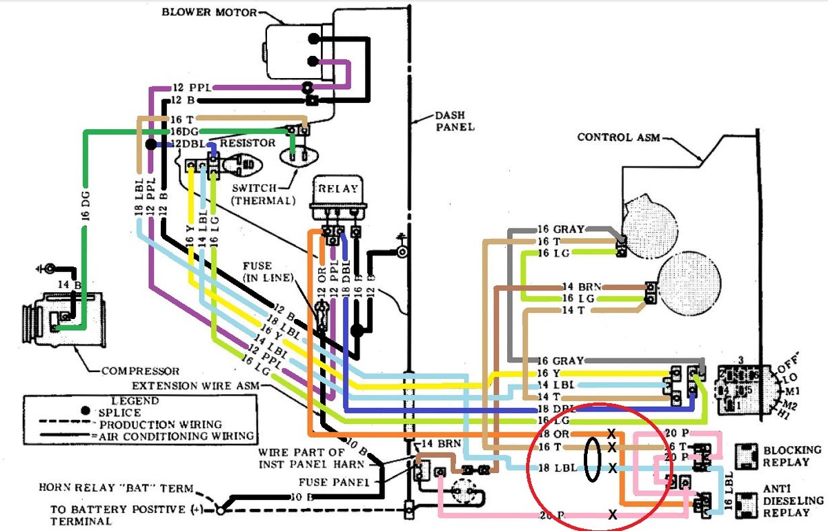
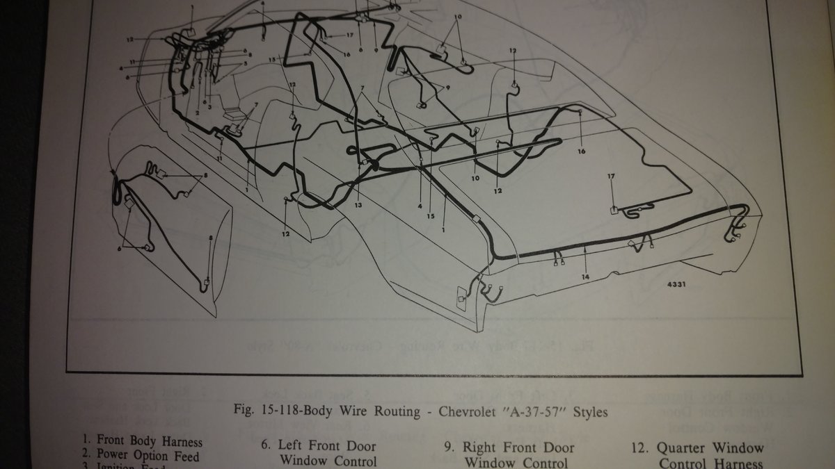
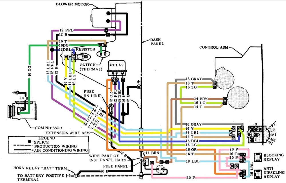
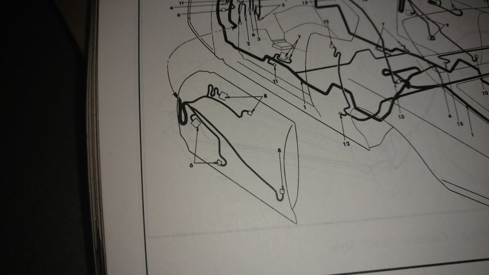
Cheap gas caused engine run-on, also known as dieseling. GM set idle speeds on cars with AC a little higher so they wouldn't stall when the AC compressor kicked in. This caused the engine to sometimes run on when the key was shut off. Their cure was to turn on the AC clutch for a few seconds when the key was turned to off. The load of the compressor stopped the engine. Again, this was for 1971 & 1972 cars, not 1970 cars. If you don't think you need this feature, it's easy to bypass. The relays and wiring are under the dash above the glove box. Looking at the diagram below, cut the wires marked with an X and splice together the light blue and tan wires. Tape off the cut wire ends. The bolt that holds the relays in place also connects the lower dash to a body brace so if you remove the relays, put the bolt back in the metalwork.

-
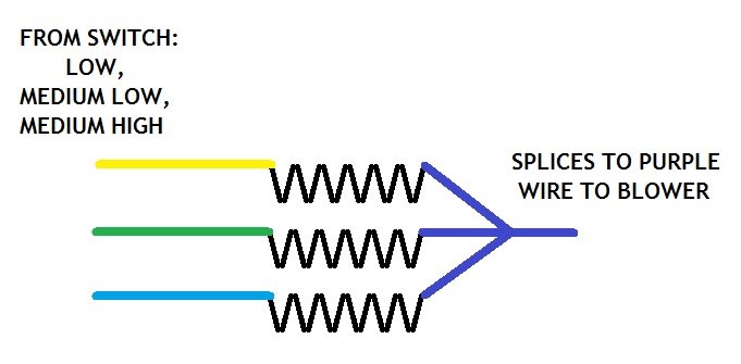
The tan, light blue and yellow wires from the blower speed switch each feed power into one of the resistors. Each resistor is then tied together and comes out of the resistor connector as a dark blue wire which splices in the harness to the blower motor wire. When you go to high speed, none of the resistors are powered. A dark blue wire from the blower speed switch sends power to the coil in the underhood blower relay which closes and sends full power to the motor. In low, low medium and medium, the motor, through the blower speed switch and resistors, is powered from the dash fuse block heater/AC fuse. When in high speed, it's powered from the relay which has the separate underhood fuse fed from the horn relay buss. Question for you: Are the four wires in the resistor plug or has the plug been cut away and you just have four loose wires?
-
Best product to use on the vinyl top
Paul Bell replied to 70chev's topic in General 70-72 Monte Carlo Forum
This stuff. Autozone has it.
-
Looks good Mark! Here, I fixed the pic for you.
-
Doug, I believe you're working on a 1971 car. 71 & 72 cars had the anti-dieseling & blocking relays above the glove box. The thinner (18 gauge) orange wire is a power feed from the underhood relay feed (from the underhood in-line fuse) to feed the anti-dieseling & blocking relays. It's the only thin orange wire in the system. How does it all work? The anti-dieseling relay sends power to the AC compressor for a few seconds after you turn the ignition key off to help stop the engine. The blocking relay prevents the powered AC wire from back feeding into the ignition switch which would keep the ignition powered-and the engine running. It does sound like your harness has been hacked up so I would ignore what somebody else did and start over. There's an easy way to eliminate the anti-dieseling & blocking relays. Here's the proper wiring diagram for this stuff.
-
Wayne, I realize this might not be very clear. These smaller 18 gauge wires are for the trigger coil on the relay.
-
Decoding Body Tag Page Updated
Paul Bell replied to Canuck's topic in General 70-72 Monte Carlo Forum
No blue vinyl roof in 1972. -
What did you do to your Monte Carlo today?
Paul Bell replied to Canuck's topic in General 70-72 Monte Carlo Forum
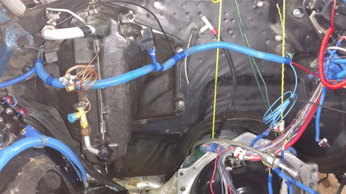
I’m finally buttoning up my AC system. The new two pass condenser is done and I closed up most of the gaps with roofing tin. It’s been handy to have a roll of it kicking around! I have the original fuse box fed from a 30 amp fuse (I have a high power fuse block under the hood). It only feeds the body lights, radio and triggers relays for everything else (EFI system, fuel, vacuum & water pump, fans, etc). Last summer, I had a 20 amp fuse feeding it and it blew, the entire car died. 30 holds fine. Keeping this in mind, I didn’t want the AC system on the original fuse block. Although high speed is from the underhood inline fuse holder, all other fan speeds come from inside. At second from high fan speed, this looks to be about 15 amps. I rewired it to be fed totally from under the hood. A new relay over the glove box provides power when the key is on. I was actually able to pull out a 18 gauge wire from the cowl AC grommet and pull in a new 12 gauge wire. I also eliminated the anti-dieseling and blocking relays. The blower speed switch is bad. 30 bucks will get a new one. All I need is an engine in place so I can finalize the AC hose lengths.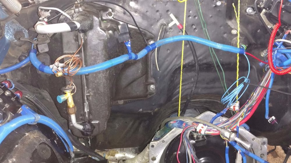
-
Sorry for the delayed response. It's said that a HEI distributor runs at 5 amps but many say it can spike as high as 20 amps so it's usually put on a 25 amp circuit. 12 gauge is only needed for the battery power in and distributor feed wires. You can feed the coil with much smaller like 18 gauge.
-
I believe if a new switch has extra terminals, the Monte plug will just leave them exposed. It's still good to use it.
-

-
It's never a dumb question! You originally stated that the HEI was on the IGN tab on the fuse box which we see is fed from with the turn signal fuse. I would assume you overloaded the circuit with the load of the turn signals and the HEI. Removing the HEI from this circuit would reduce the amps on the fuse. The HEI would now have it's own independent feed. HOWEVER, if the turn signal fuse blew for some other reason such as a bare or worn through wire grounding somewhere, it could happen again. Remember, it's this circuit that triggers the new relay. So, if the fuse blows again, the relay opens and the HEI loses power.
-
Yes, there is a better way. Install an in-line fuse holder at the battery, connected to the battery positive. Mount a relay somewhere on the firewall and a 12 gauge wire to it from the fuse holder. Use the IGN feed to trigger the relay. Then feed the HEI. Fuse it at 25 amps. Run the wire carefully. All this takes the load of the ignition out of the fuse box-and the load of all the body lights. A direct battery feed is always better and more reliable. This makes it easy: https://www.ebay.com/itm/Car-Auto-DC-12V-Volt-30-40A-Automotive-4-Pin-4-Wire-Relay-Socket-30amp-40amp-US/183631568498?hash=item2ac14b5e72:g:SToAAOSwqoxcOKhy

-
I made my own.