MCfan
-
Posts
1,294 -
Joined
-
Last visited
-
Days Won
61
Content Type
Profiles
Articles
Forums
Gallery
Events
Everything posted by MCfan
-
Paul, The 1970 Monte specs I have do not list front shock travel directly, however, I think you can back into it from the specs given. Here's the data I have: Wheel travel (design): Total 7.92" Jounce 3.92" Rebound 4.00" Wheel to spring travel ratio = 1.86 Since the front shock is mounted in the center of the front coil spring, that 1.86 travel ratio should apply to the shock travel just as it does to the spring. So, 7.92" (total wheel travel) divided by the 1.86 ratio would yield 4.25" of shock travel. Note that the data above is the design spec so maximum shock travel may be a bit more (but certainly not less). In any case 4 1/4" of shock travel seems reasonable to me. The only front shock specifications provided in the 1970 Monte Specs are: Type = Direct, double-acting, hydraulic Piston diameter = 1" BTW, if you are wondering about a taller than stock coil spring being compatible with a given shock travel, remember that all front coils, once installed, have the exact same working height of 11.7". The spring rate also has to be considered. For any given spring rate, a taller spring will simply increase the preload weight (spring height - 11.7") x spring rate #/in. Greater preload will cause the front end to sit higher and thereby change the transition point between Jounce and Rebound specs but when you apply the 1.86 ratio, that will have a very small affect on shock travel. Of course, the jounce/rebound ratio on the shock you select will have an affect on ride performance but not travel. Although that spec is not given, I assume it is 50/50 as most shocks at that time were. Hope this information is useful. Someone else may have the exact spec you are looking for.
-
What did you do to your Monte Carlo today?
MCfan replied to Canuck's topic in General 70-72 Monte Carlo Forum
Good choice! Love my plastic inner fenders from the Parts Place! -
Sounds like you are building another wicked street machine, Andy! Wonder how you will hook all that HP (and torque) to the pavement? Really appreciated your tribute to CrazyDavey - this club suffered a real loss at his passing, IMO. Do you possibly know what became of his white '67 Chevelle - just wonder if it was retired or if someone else is campaigning it on the west coast? Doubt anyone could make it go faster than Davey did! Also wonder what became of his wife's black '72 W code Monte - hope it is still in circulation.
-
Sendo, The rear bumper on my SS was not bent but the brackets needed realignment with the frame. I removed the bumper (as you also have done) and then removed the brackets so I could clean and re-paint them. I sprayed the back side of the bumper with Bumper Chrome by Plastikote and sprayed the brackets with Rustoleum semi-gloss black. I inspected the brackets for bends but found none. When I remounted the bumper to the frame, I aligned it the way I wanted and it bolted right up. At that time my rear bumper did not have bumper guards (I mounted a pair several years later) so maybe the bumper was pushed out of alignment when someone tried to push the Monte from the rear. I guessing you can remount your bumper in the correct position. You may need to have someone hold it in place while you tighten the bolts. Good luck.
-
Oh, sure, her husband placed a "value" of $40K+ on his favorite classic car ... dream on. What will the market actually bear? I can't believe a "professional appraiser" will come up with anything north of $30K, if that. We're talking LS3 here, not LS6 ... Just stay in touch with the wife and try to learn what the appraiser comes up with car by car. I'm betting the original dealer low-balled her on the other three in order to offer her a big price for the Monte (maybe he knew her husband's expectation). Doubt he would be willing to do anything but a package deal. Keep your powder dry and reason with the wife after she has a more realistic appraisal ... this might come back your way after all - I hope so. Good luck!
-
That's quite a story with a disappointing outcome for you, Rob. That lady should dump that dealer or at least get another dealer to appraise them. If she really wanted to honor her late husband's wishes, she would sell you the Monte for a reasonable price and get rid of the other three any way she can. Maybe you could offer to advertise the other three locally or even nationally on Craigslist or eBay to help her sell them in consideration for letting you buy the Monte at your appraisal price. I had a similar experience when my wife's uncle passed suddenly of a stroke several years ago. I had helped him build a complete record with individual photos and appraisal prices on his large gun collection easily worth $45K. I foolishly provided those detailed records to his worthless son-in-law thinking we could discuss it and I could make him an offer. Instead, without my knowledge, he loaded up all the guns and a huge gun safe and took them to a dealer who offered him a take-it-or-leave-it $15K when I would have written him a check for $25K on the spot. I immediately went to the dealer to buy the only rifle I wanted for my collection but he was asking more than new retail price so I passed with nothing to show for my work and no keepsake from my uncle's collection. Some people are just greedy, thoughtless and heartless, I guess. I hope something still works out for you as I share your love of big block 4-speed Montes, as you would know.
-
First, welcome to the club and forums, Paul! Second, I think you must be an ambitious, talented and experienced car guy to take on the project you described. While almost all of that is way beyond me, there are other members that can walk with you through most of it. I just hope you have the time, resources and patience to see your dreams fulfilled. Some of us have to live vicariously through the accomplishments of others so don't be bashful about sharing your progress - we love photos. Good luck!
-
Sendo, It appears from your photos that you are running a Holley spread-bore on a stock manifold. Your distributor's vacuum advance is currently connected to the "timed" (or ported) vacuum port on the metering block of your Holley carb (as shown in your first photo). If you want to switch to "full" (or manifold) vacuum for your distributor advance the answer to your question is "Yes". Remove the black cap from the port at the front base of your carb (as shown in your second photo) and connect your distributor's vacuum line to it. Then place the black cap on the port where you just removed the vacuum line on the side of the metering block. As discussed in the thread above, you may or may not have to tweak your initial timing when you switch between timed and full vacuum advance. I'd just try it first and mess with initial timing only if I got some pinging. Good luck.
-
Cool - even has running lights in the windshield visor! I'm guessing a C15 is a two-wheel drive 3/4 ton but my pickup interest, awareness and nomenclature has never matched the autos. Great that you have something out of the ordinary to enjoy with your son - he's a luck kid!
-
Frankly, Tom, I would pass on both of those and just contact Steve Redmyer (sredmyer) in this club. He has a stable full of '70 SS models including one or more triple black beauties. Not sure if he is ready to let any go right now, but he has been known to in the past. Good luck.
-
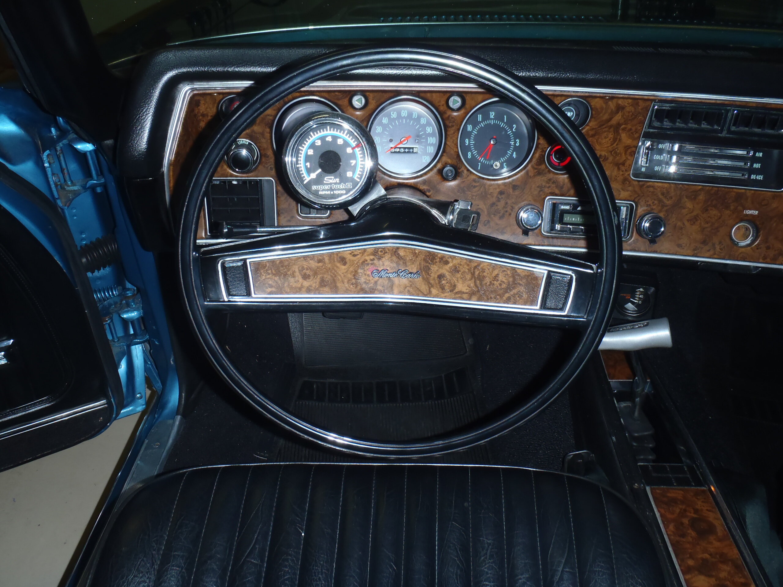
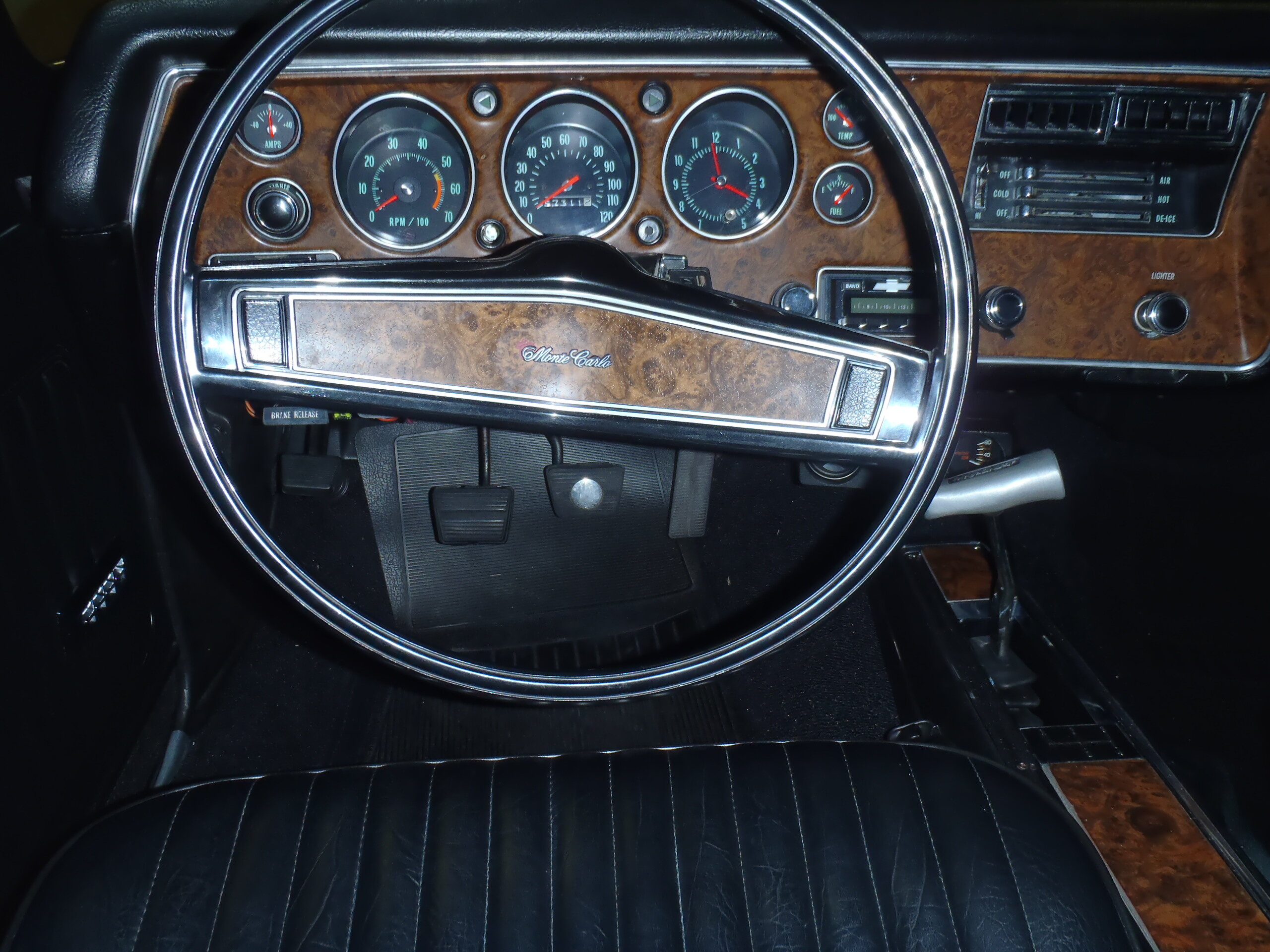
Hey, Tom, You can easily convert your idiot light dash to a full gauge dash that is identical to the factory option using a kit and you DO NOT have to replace your current wiring harness, just add a couple of new wires and make some necessary modifications to various specified plug/connector locations. There is a seller on eBay named sonnie24 who offers the complete conversion kit to do this (be sure to specify the '70 kit to get the green shaded numerals on your gauges). The kit includes the tach, analog gauges, wires and a new printed circuit board. It is reasonably priced and uses quality components, however, the 2-page instructions that come with it assume a lot of knowledge that many of us don't have. When I did this conversion on my '70, I sought the help and advice of Darren Bull (LS5), fellow club member who knows first gen Monte dash wiring cold. Together we developed a detailed set of instructions with diagrams that make the conversion almost fool-proof. If you want, send me your email address in a Private Message, and I will forward a copy of that documentation to you in a Word file. It also contains links to a couple of photo journals on Photo Bucket showing the installation process (including upgrading your dash illumination from the original incandescent bulbs to LEDs and repairing your dash clock while you have the dash apart). This is not a plug and play conversion so it takes some time and work but the results are very satisfying. Good luck. Here are the Before and After shots on my '70:


- 11 replies
-
- 3
-

-
- dash
- tachometer
- (and 1 more)
-
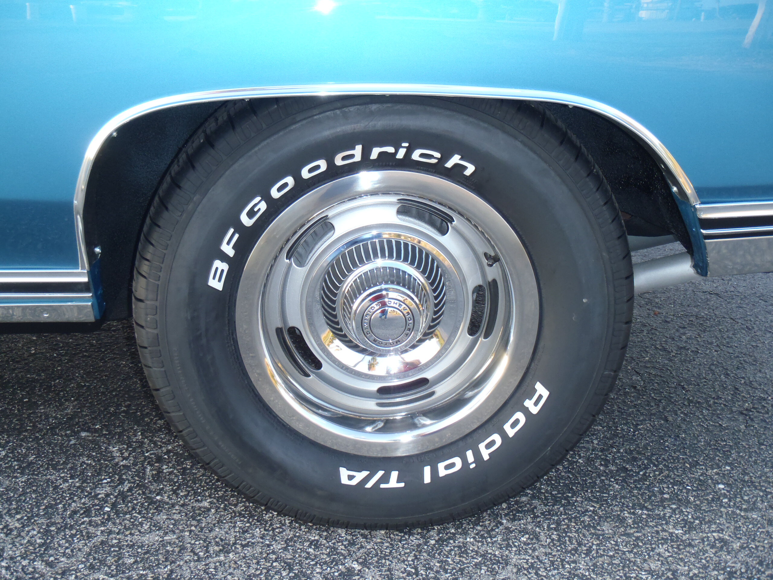
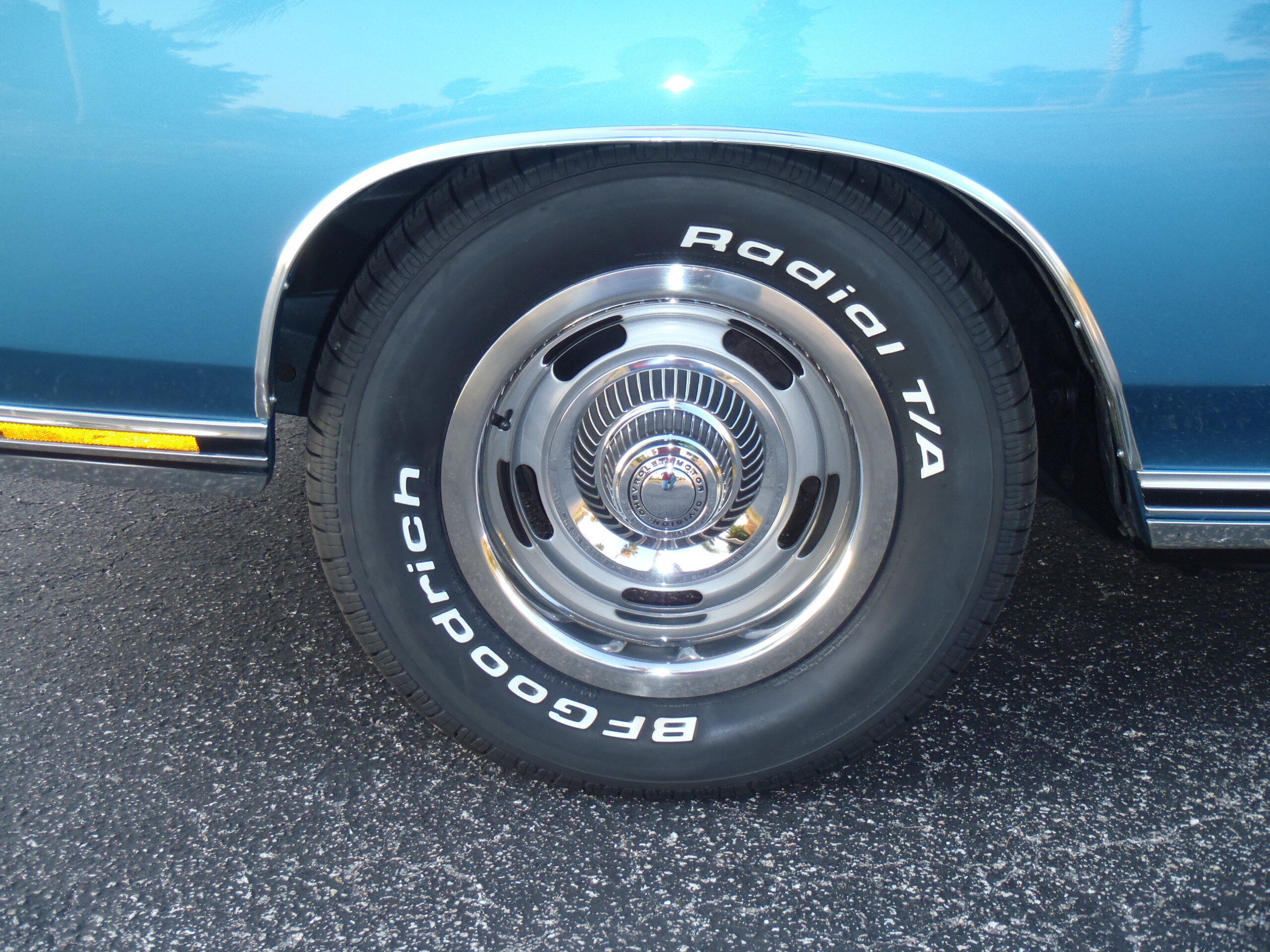
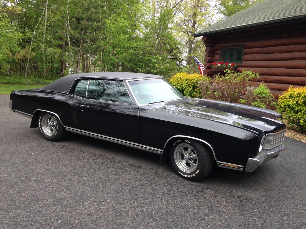
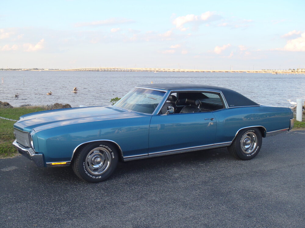
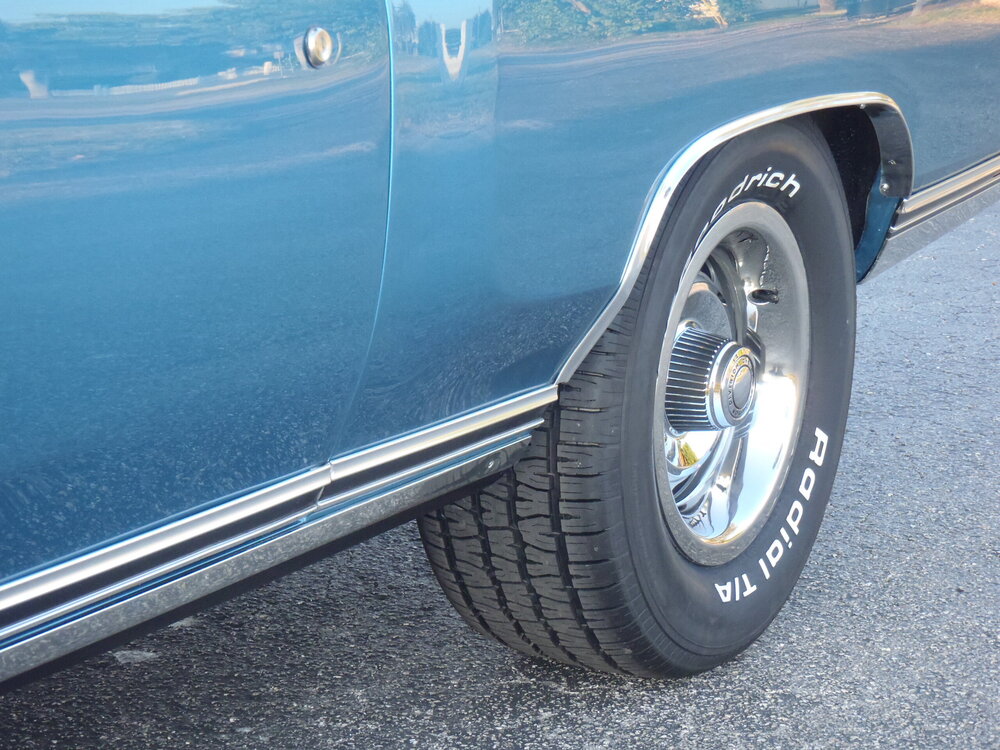
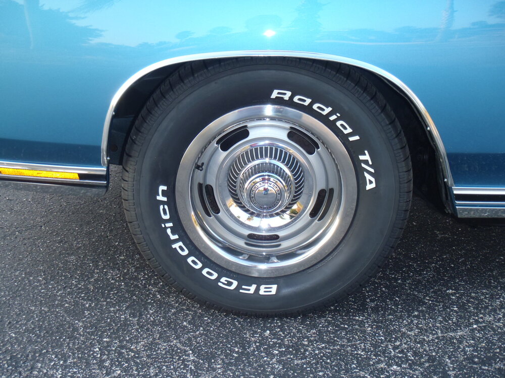
Ok, here you go: 275/60-15 BFGs on 15x8 Wheel Vintiques rally rims with 5.5" BS on the rear. That backspace will give at least 3/4" clearance between the sidewall and the unmodified wheel opening lip on the rear quarter. It also allows the use of 3'" deep dish rally trim rings as shown in the photos below. Only a 4" BS is needed on 15x7 rims in the front to accommodate the same deep dish trim rings.

-
70 vinyl top early and late year
MCfan replied to Montebo1970's topic in General 70-72 Monte Carlo Forum
A vinyl top was a popular option that could be ordered as RPO C08. Two tone paint was also an option. See the Tech Info section of this site to see the possible color combinations. -
Can’t find in Forum but I know it’s there
MCfan replied to Dtret's topic in General 70-72 Monte Carlo Forum
Yes, the brown wire that came in your kit is undoubtedly for the tach, As you may already know, that wire must be routed through the firewall and connects to the negative terminal of your coil (or the tach port on an HEI). The other end of the brown wire plugs into position 9 of the wiring harness connector to the new PCB. From the instruction document: Connecting the brown (tachometer signal) wire to the coil: 1. A 3/8” hole should be drilled through the firewall (from the engine side) at the dimple about 1 inch below and slightly to the right of where the throttle cable comes through the firewall. 2. Insert the loose end of the brown wire through the hole in the firewall and insert the grommet in the hole to protect the wire from abrasion, 3. Connect the loose end of the brown wire to the negative (-) side of the coil or to the Tach Port of an HEI distributor. I am somewhat confused regarding your statement that there are/were two temperature wires but maybe this is what you are seeing: The dark green wire originally in position 9 of the wiring harness connector is the temperature sensor wire. The pink wire originally in position 5 is a fused power line for the fuel, temperature, brake and oil pressure lights. There was absolutely no mention of TCS in any instructions I have ever seen for this conversion and I did not connect any wires for a TCS system as mine was long since entirely removed from my '70. This conversion calls for the dark green wire to be re-plugged into position 10 and the pink wire into position 7. Again, from the instruction document: Rewire and add wires to the main instrument cluster plug: 1. Locate the main instrument cluster plug which is the one you unplugged from the back of the cluster housing before you removed it from the dash. 2. Refer to the lower diagram on the page above. Carefully inspect the plug and note the color of wire currently at each of the 12 available connector slots. NOTE: the slots are numbered at the bottom of the plug. 1-6 on one side and 7-12 on the other. Slots # 4 and #6 should be empty/available slots. 3. Wires located in slots 1, 2, 8 and 12 will NOT be moved so leave them alone. 4. Remove the brown (generator) wire in slot 3 by inserting a very tiny (eye glass) screwdriver between the flat side of the connector and the connector housing until the retaining barb unhooks and then pull the wire and connector out of the housing. This wire will NOT be used again so either tape that connector with electrical tape or cut it off or both. 5. The five remaining wires will be used but must be temporarily removed from the plug using the same technique as for the brown wire above. Be sure to reset the retaining barb on each removed connector by bending it out slightly so it will stay in place in its new slot. 6. Install the wire connectors into new slot positions in the plug as follows: a. Plug the light green (high beam) wire into slot #5 b. Plug the dark blue (oil pressure) wire into slot #6 c. Plug the pink (tach/temp/brake/oil: fused power) wire into slot #7 d. Plug the dark green (temperature) wire into slot #10 e. Plug the tan (fuel) wire into slot #11 7. Add new wires from the kit to the main cluster plug as follows: a. Plug the short black/white striped (ammeter) wire into slot #3 b. Plug the short black (ammeter) wire into slot #4 c. Plug the brown (tachometer signal) wire w/rubber grommet into slot #9 8. All 12 slots in the main cluster plug should now be filled and there should be three new (a short black/white striped wire, a short black wire and a longer brown wire) 9. Refer to the lower plug diagram below to check your work. Hope this helps. -
Can’t find in Forum but I know it’s there
MCfan replied to Dtret's topic in General 70-72 Monte Carlo Forum
It's no bother to send you the Word file with detailed instructions, Dennis. My only concern is if the '71 dash is wired the same at the '70 dash for which my instructions are written. I just reviewed my instructions (glad I wrote that document while I did the conversion because there is no way I could have remembered all those detailed steps) to see if I could identify your left over brown wire. I believe it may be the brown generator wire that originally ran from the horn relay to position 3 in the wiring harness connector to the circuit panel. That wire is not used for the full gauge dash in a '70. My instructions say to remove its connector from position 3 and either cut it off or tape it off. Perhaps you removed the wire entirely and that is what you now have left over. In any case, I will be happy to send you the detailed instructions if you think you can use them. -
Can’t find in Forum but I know it’s there
MCfan replied to Dtret's topic in General 70-72 Monte Carlo Forum
Dennis, I wrote a more detailed set of instructions for the Sonnie24 full gauge dash conversion but it is for a '70. I believe you are converting a '71 so I am not sure they are the same (I know a '72 is different). If you will PM me with your email address,, I will send you the Word file with the more detailed instructions and illustrations. Thanks. -
You will find strong preferences for either plastic or steel "replacements" but there is nothing "stock" about steel inner fenders unless you'd rather your Monte was a Chevelle. I have used both types in my '70 Montes and both get the job done, but I far prefer the plastic ones made for and sold by The Parts Place, Inc. They are made specifically for first gen Montes (not Chevelles), fit perfectly, are much easier to remove/install than steel and are made of a modern more flexible plastic that won't crack like the originals. Now, I'll stop and let others tell you why the steel inner fenders are wonderful ...
-
Dang, Mark, you got it 1/4" off! jk
-
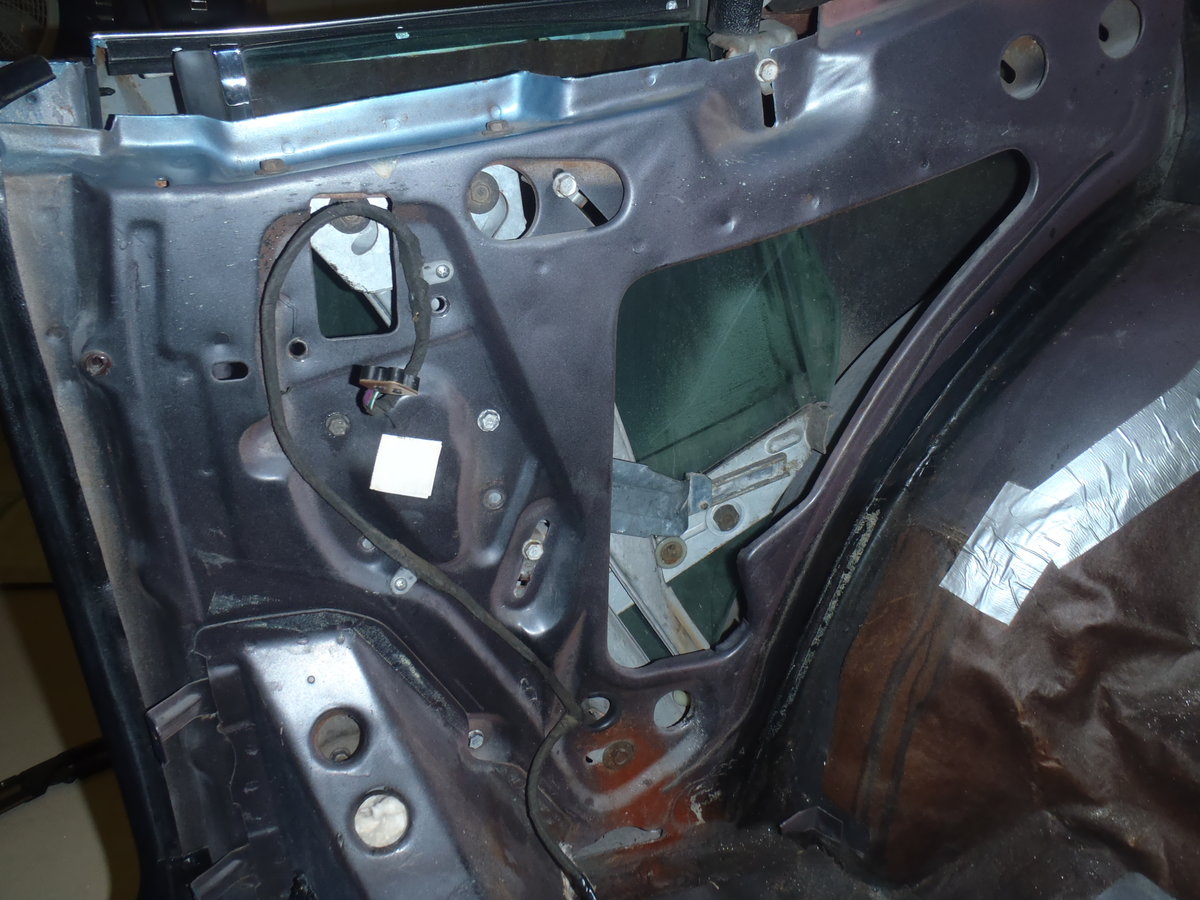
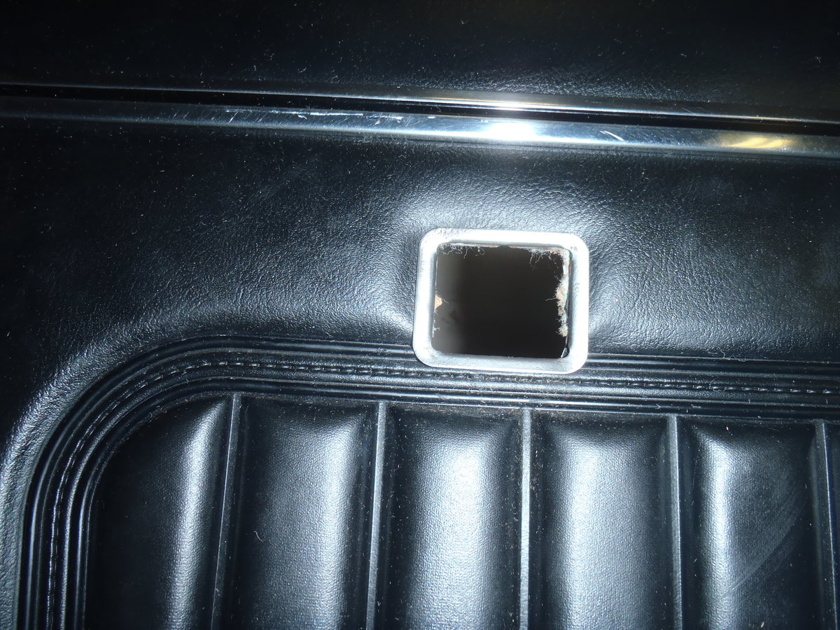
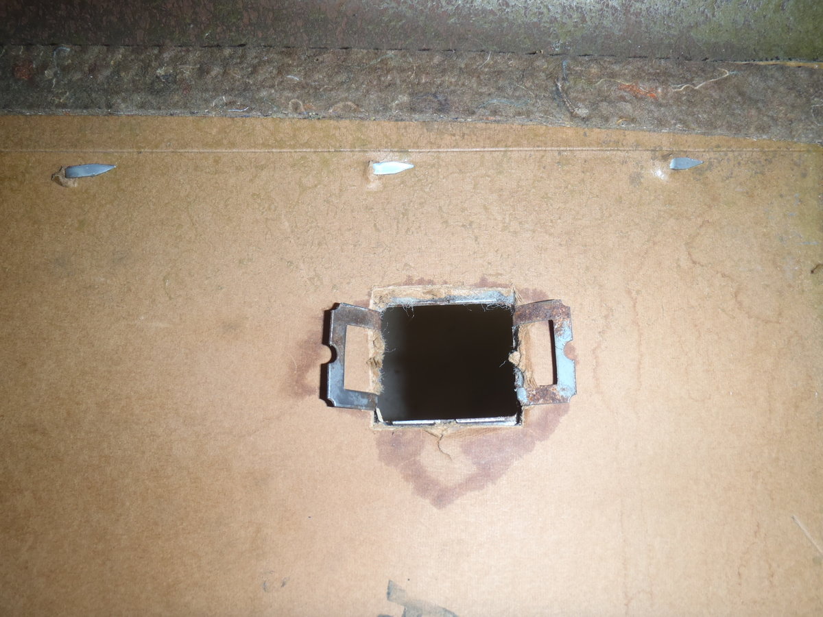
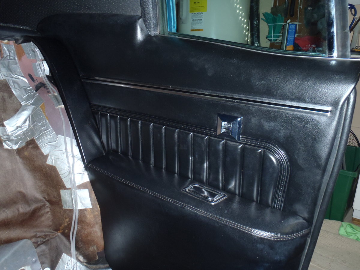
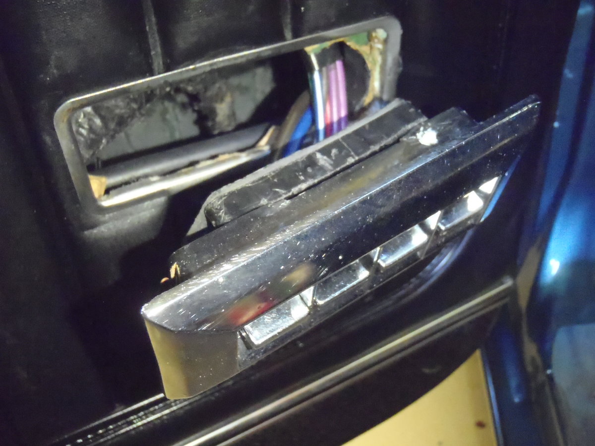
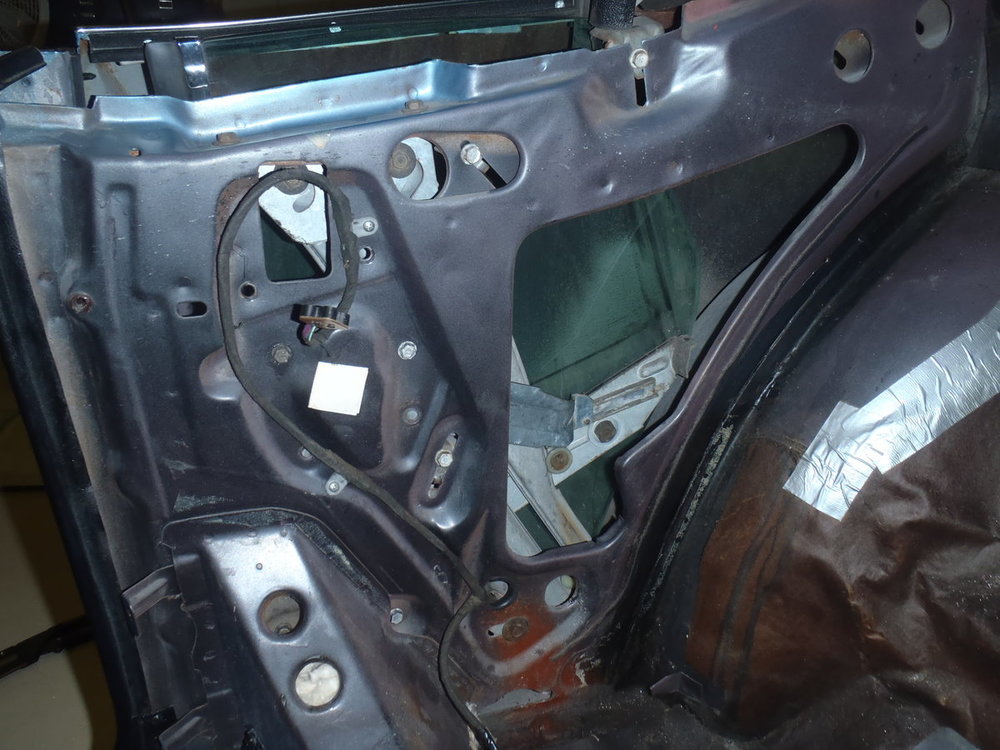
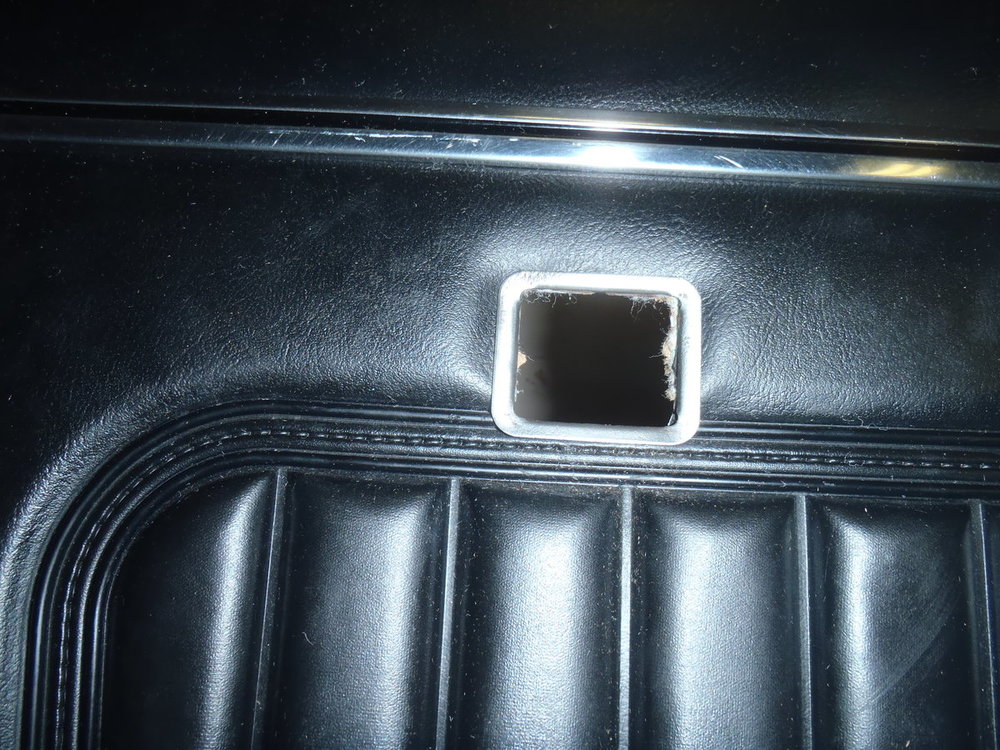
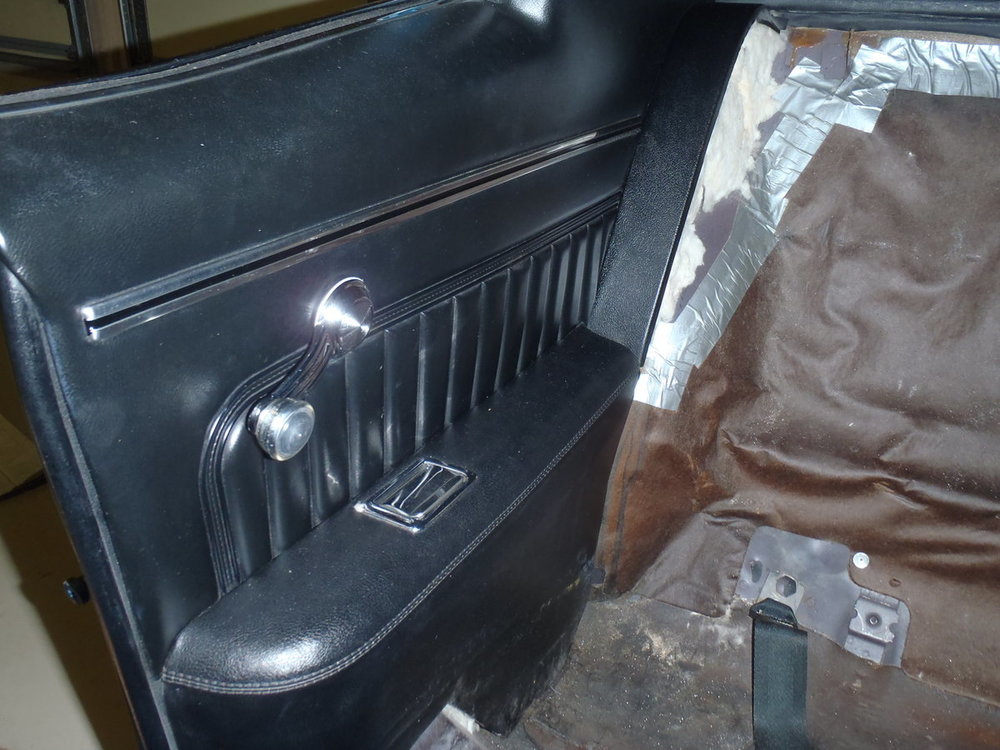
Hey, Mark, if I am understanding your question, the location of the power window switch in the rear door panels is exactly where the hole is for the former window crank. Just position the rectangular switch mounting frame over that hole and enlarge the round hole to the rectangular shape with a box cutter.


-
Wow, Ron, that's beautiful work! Far nicer than new ... well done!!
-
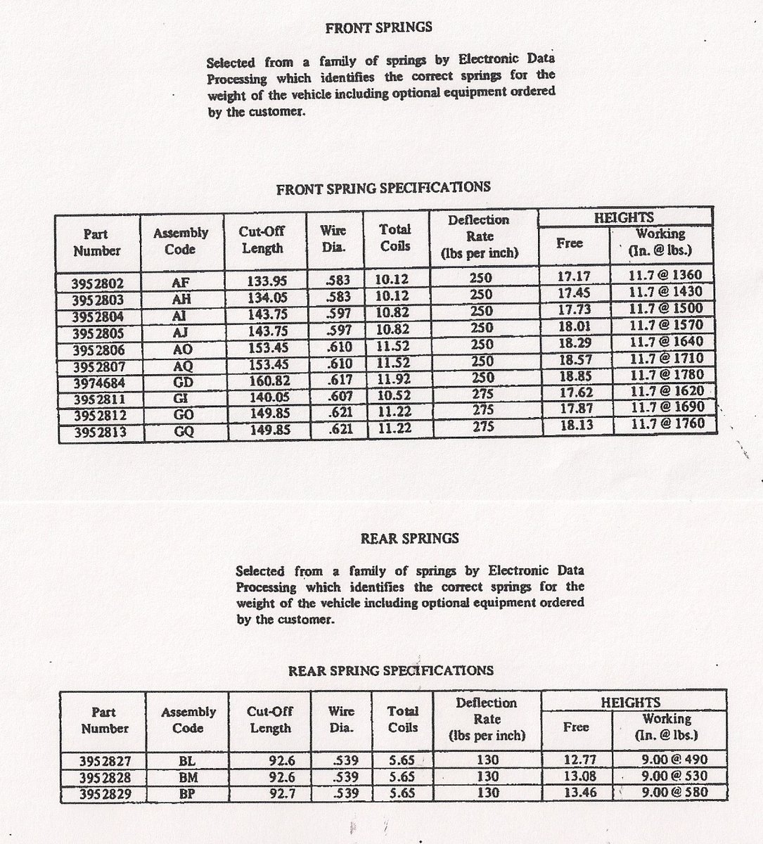
The table I shared is from the 1970 Monte Carlo Specifications document so it is possible that different/additional spring codes were used in '71 and '72. Yours is the first build sheet I've seen that has a different code but perhaps there are others. Maybe someone has the 1971 Monte Carlo Specifications document that shows the table of possible springs/codes used that model year. If the "AK" code is in the other series of "A" codes, it would be a mid-range spring. That seems surprising to me unless your SS is a lower optioned vehicle, especially with no A/C which adds more to total vehicle weight than any other option except a big block. My big block, 4-speed '70 was a very low option car (not even power steering) and was built with the AO front spring. A heavily optioned small block car could have a higher total vehicle weight than a low optioned big block car.
-
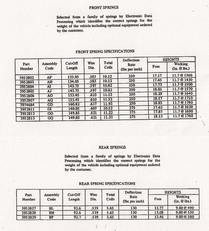
Ron, GM selected and installed one of ten possible front coils and one of 3 possible rear coils in each individual first gen Monte based on the total weight of that vehicle including all options. It had nothing to do with whether that car had a "small block" or "big block" engine as is commonly thought. You can find the "Free Height" listed for each possible spring in the table below (shown in the second column from the right). If you have a Build Sheet for your car, check Box 13 for the front spring Assembly Code that was selected for your particular car. If you have a reasonably optioned 454 car, the code will likely be GQ which has a free height of 18.13 inches. While the part number is also shown in that table for each spring, I don't believe it is stamped on the spring (unlike Moog springs which do have a stamped PN). You can also use a micrometer or digital caliper to measure the diameter of the coil wire (clean it first) and compare that to the spec given in the table. The overall free height may change over years of use but the coil wire diameter won't. Good luck.
-
I flipped mine over and use it like a tray. I'd rather have the spare tire against the jack than the jack against the trunk mat. If I understand correctly, those weren't introduced until the '72 model year but I managed to scrounge a couple for my '70s.
-
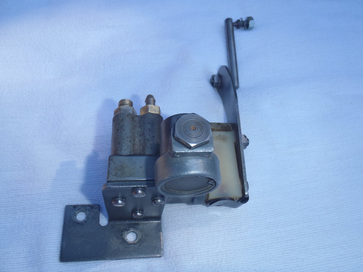
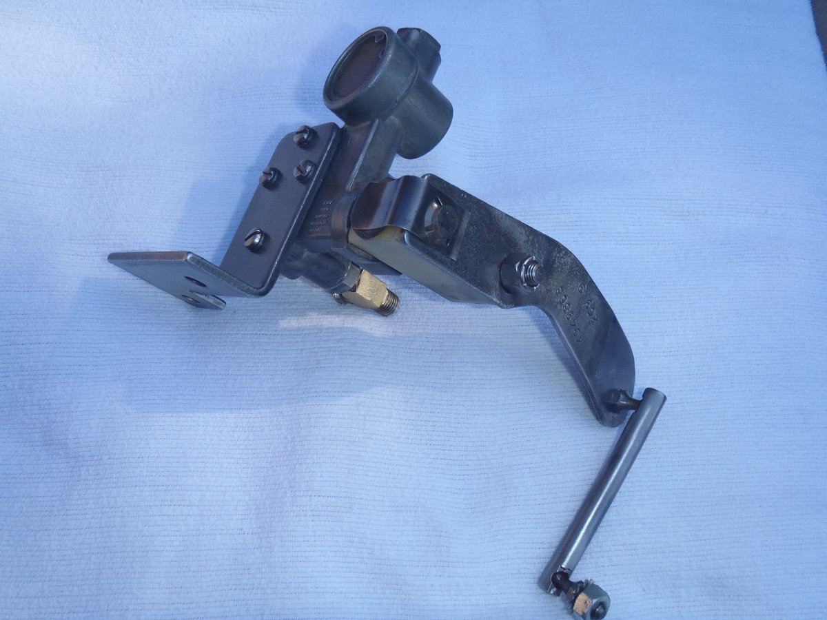
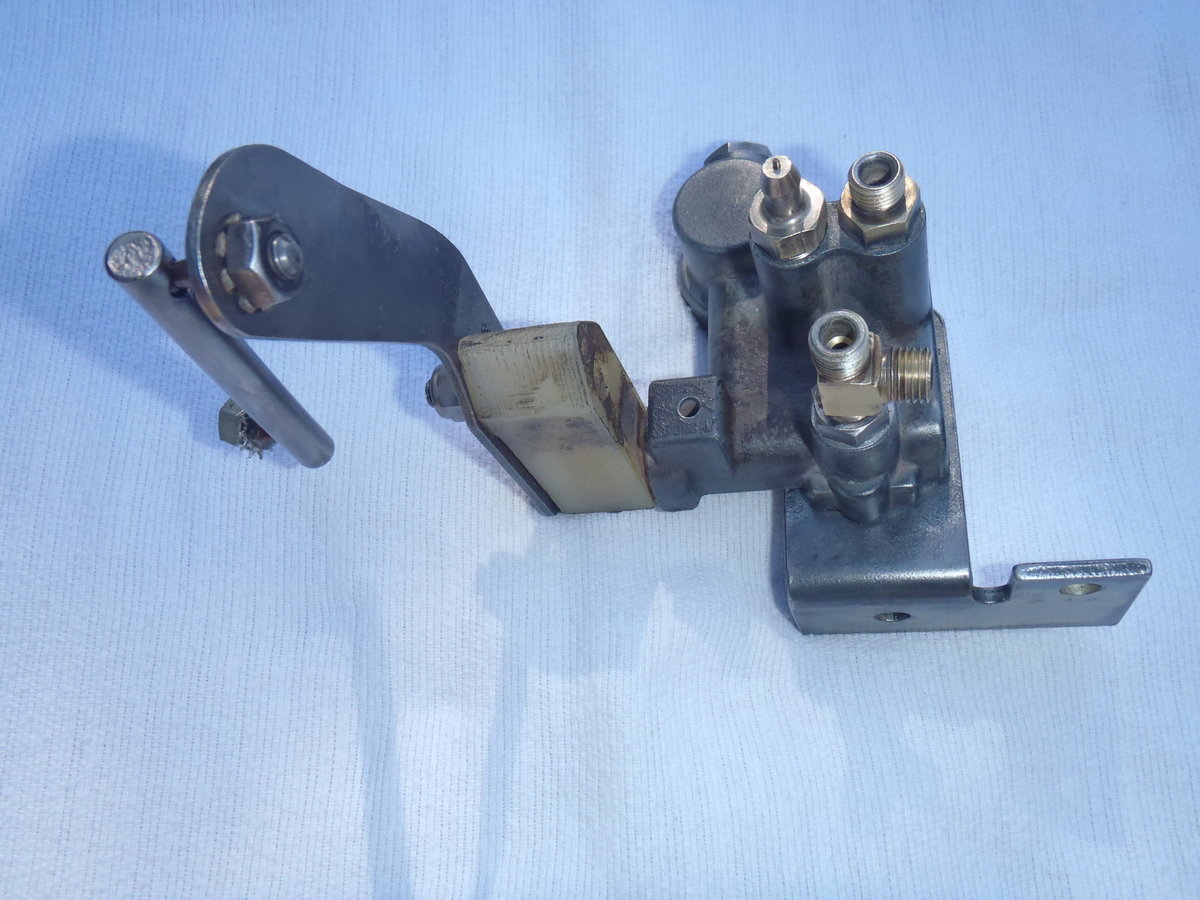
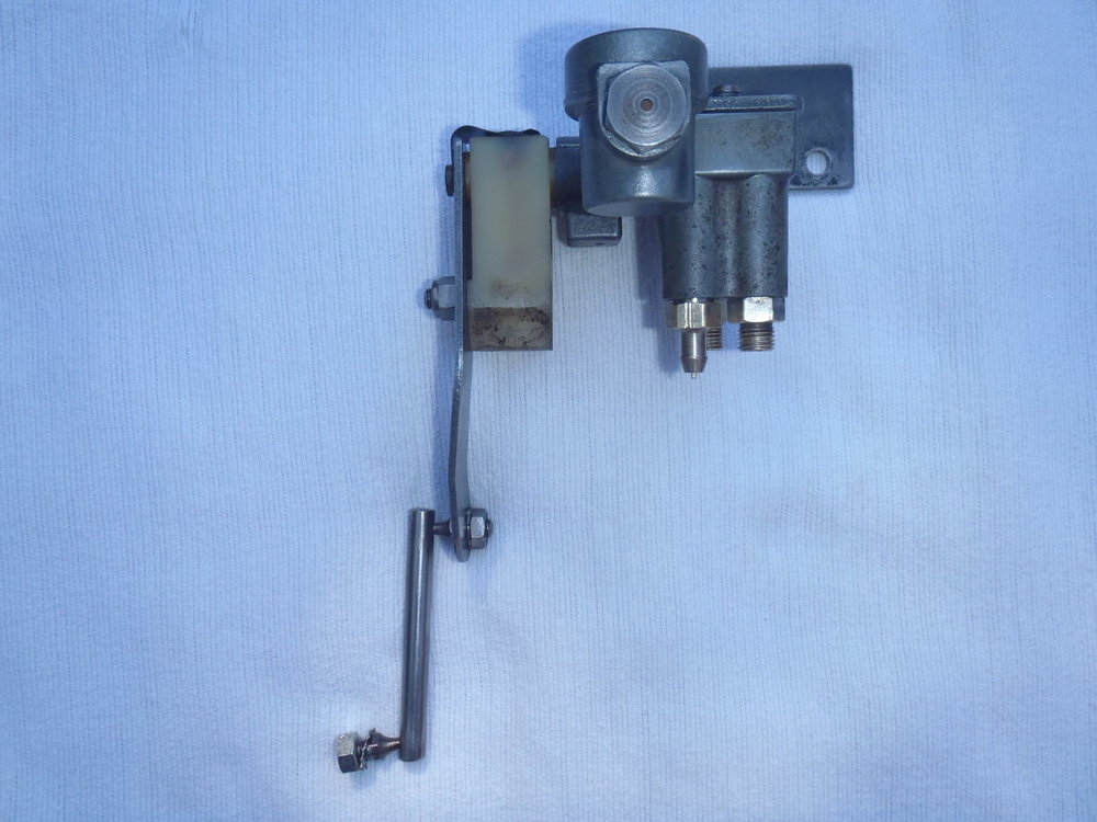
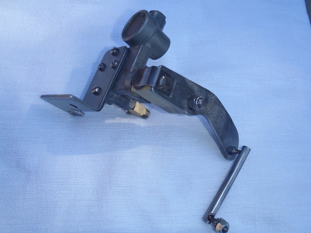
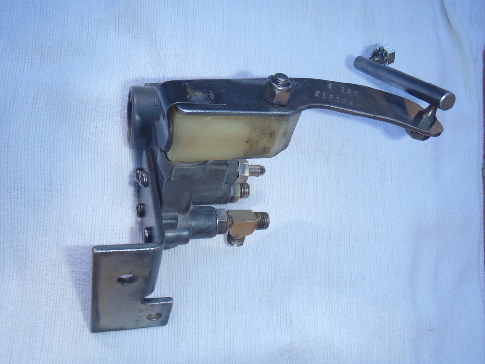
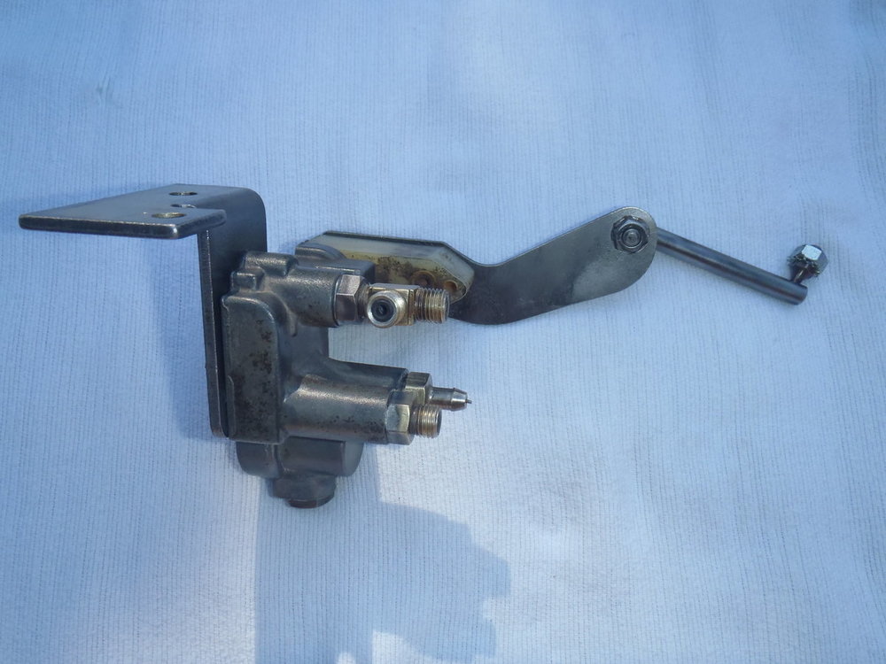
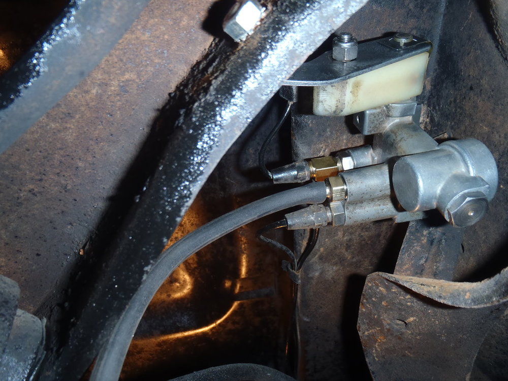
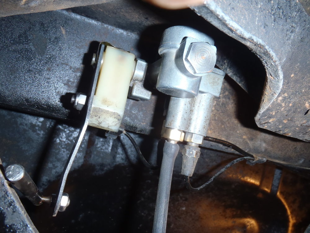
Yes, although I disassembled it only far enough to clean the exterior surfaces. I did not take the entire valve apart. I took quite a few photos but did not complete a photo journal of that project. As I recall, the primary task was to remove all of the black POR-15 that had been sprayed on the valve when the whole undercarriage was sprayed by a prior owner. As you may know, there are very few solvents that will dissolve POR-15. I used some lacquer thinner and a really stiff brush on the softer body parts and cleaned the steel arm, connecting linkage and air line connectors on my wire-wheeled grinder. While your's may not have anything as nasty as POR-15 on it, I doubt I would submerge it in water to clean it. However, if the line connectors were off so the internals of the valve were exposed to road dust and water, it might be wise to inspect and clean the inside of the valve as well as the outside. Happy scrubbing!


-
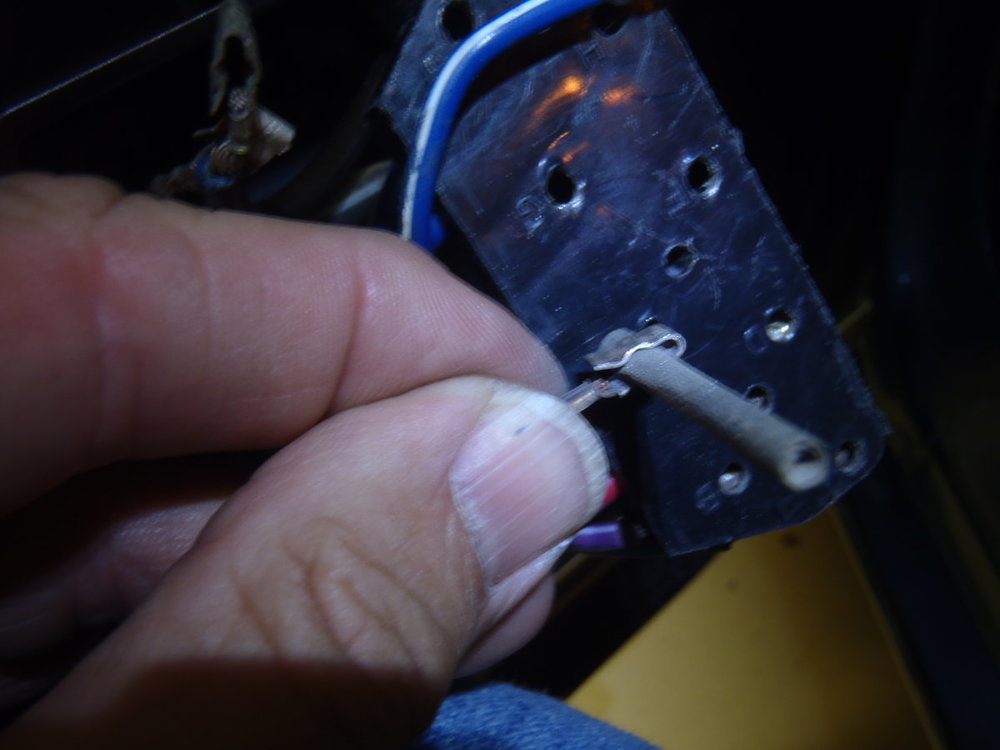
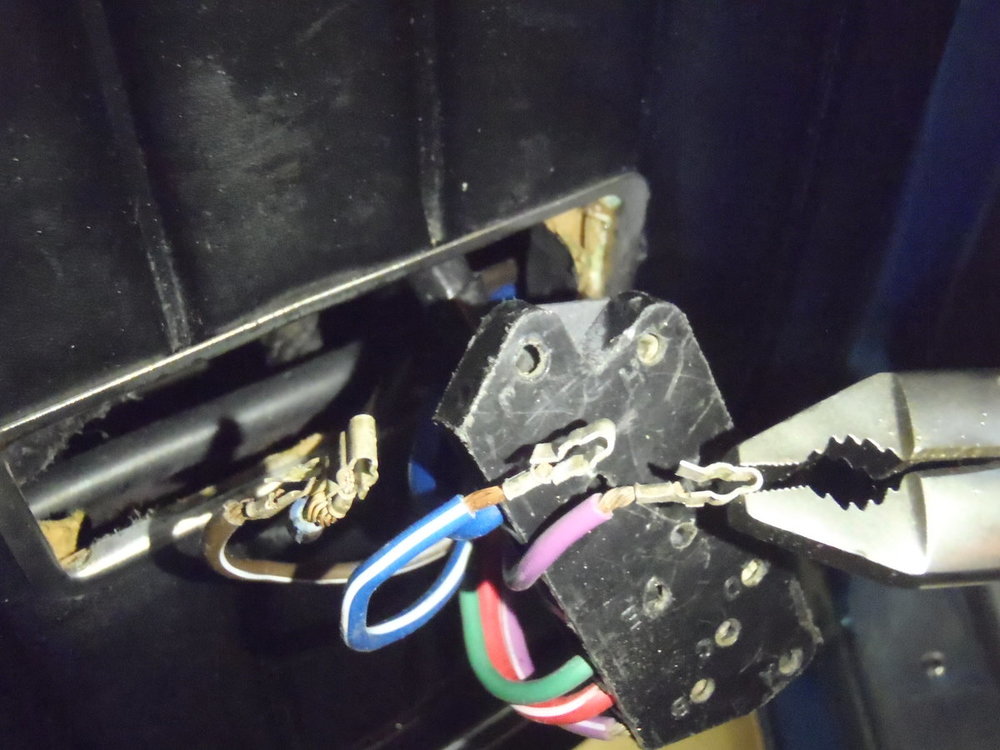
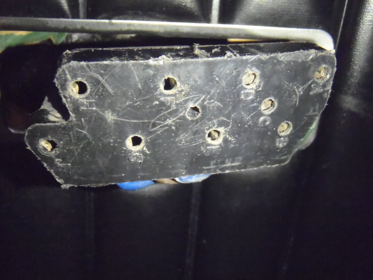
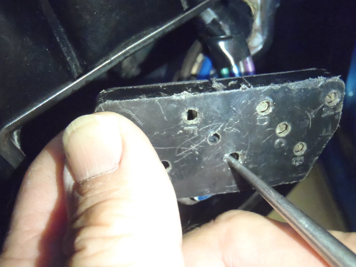
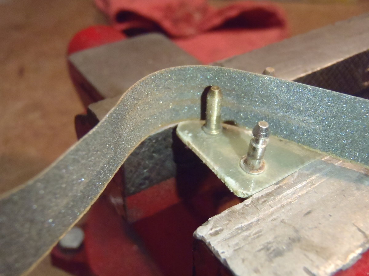
John, I've not had that problem but I refurbished all of the switches and their connectors before I installed factory power windows in my '70 (I made a photo journal of that project at this LINK if you are interested). I suspect the connector to the driver's master switch simply needs to be cleaned and tightened up and it is not difficult to do but takes some care and patience. You don't even have to remove the door panel to do it, just pop the master switch out of it's door panel housing and separate it from its connector (should be easy if it is already loose). As you can see in the photos, with the exception of the center locator pin, each of the pins on the master switch insert into a spring-clip wire terminal housed inside the black plastic connector body. Those terminals need to grip their respective switch connector pins securely for good electrical conductivity and to maintain a secure physical connection with the master switch. If you use a thin, sharp-pointed tool (scribe, awl or straight pick), you can close the spring clips just enough while pulling gently on its respective wire to remove it from the connector housing. Once you have it out, you can clean it inside with a small, rolled-up piece of fine emery paper and crimp it down just enough to give a good friction fit to a pin in the switch body. When the spring clip is cleaned and reshaped, just push it back into its correct location in the connector housing. I suggest doing them one at a time or taking a photo before you start to be sure you get all of the wires back in the correct location. Now is the best time to use some emery paper to brighten up each of the pins on the back of the master switch also. You may find that this simple fix also improves the speed and operation of any/all of the windows as good electrical conductivity is essential. Good luck.