MCfan
-
Posts
1,291 -
Joined
-
Last visited
-
Days Won
60
Content Type
Profiles
Articles
Forums
Gallery
Events
Everything posted by MCfan
-
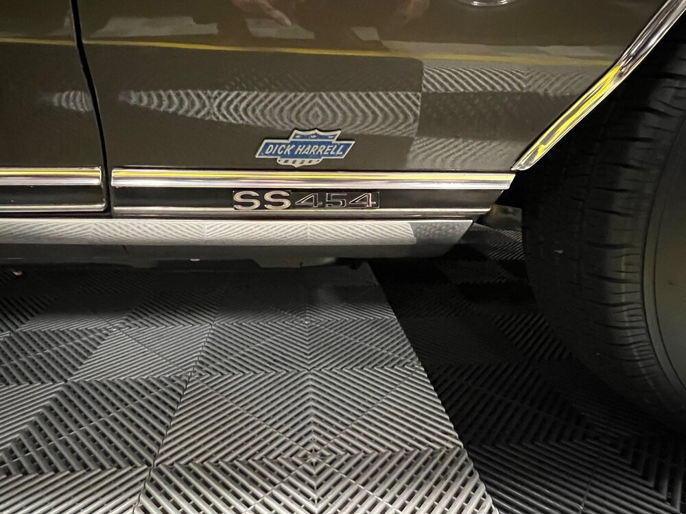
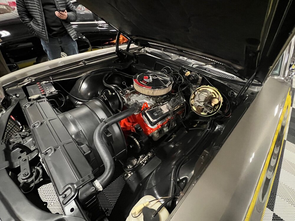
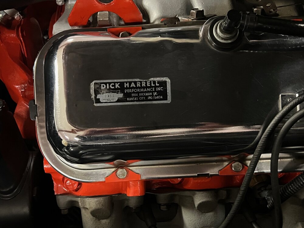
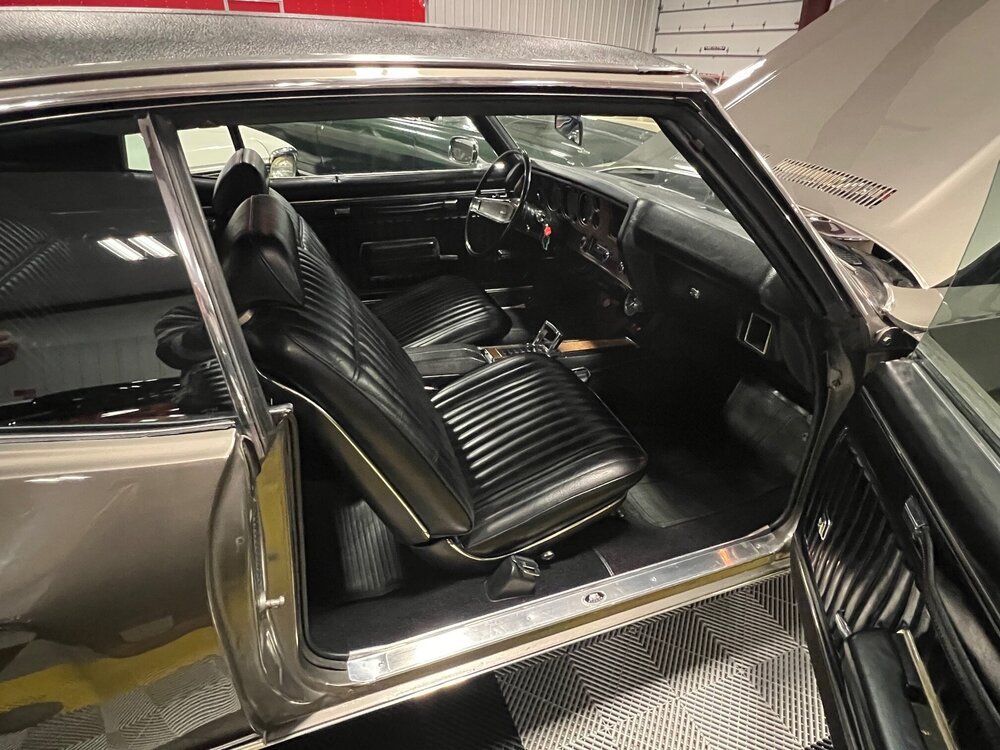
Yes, and there are a few other "personal touches" like the wheels and additional badging beyond Dick Harrell's. I believe Tim said he was the third or fourth owner and wanted to leave it largely as it came to him. One thing he did do was replace the tube headers with correct re-finished exhaust manifolds. There are several Concours d'Elegance cars among the musuem contributors so they have a wealth of knowledge and an appreciation for originality.
-
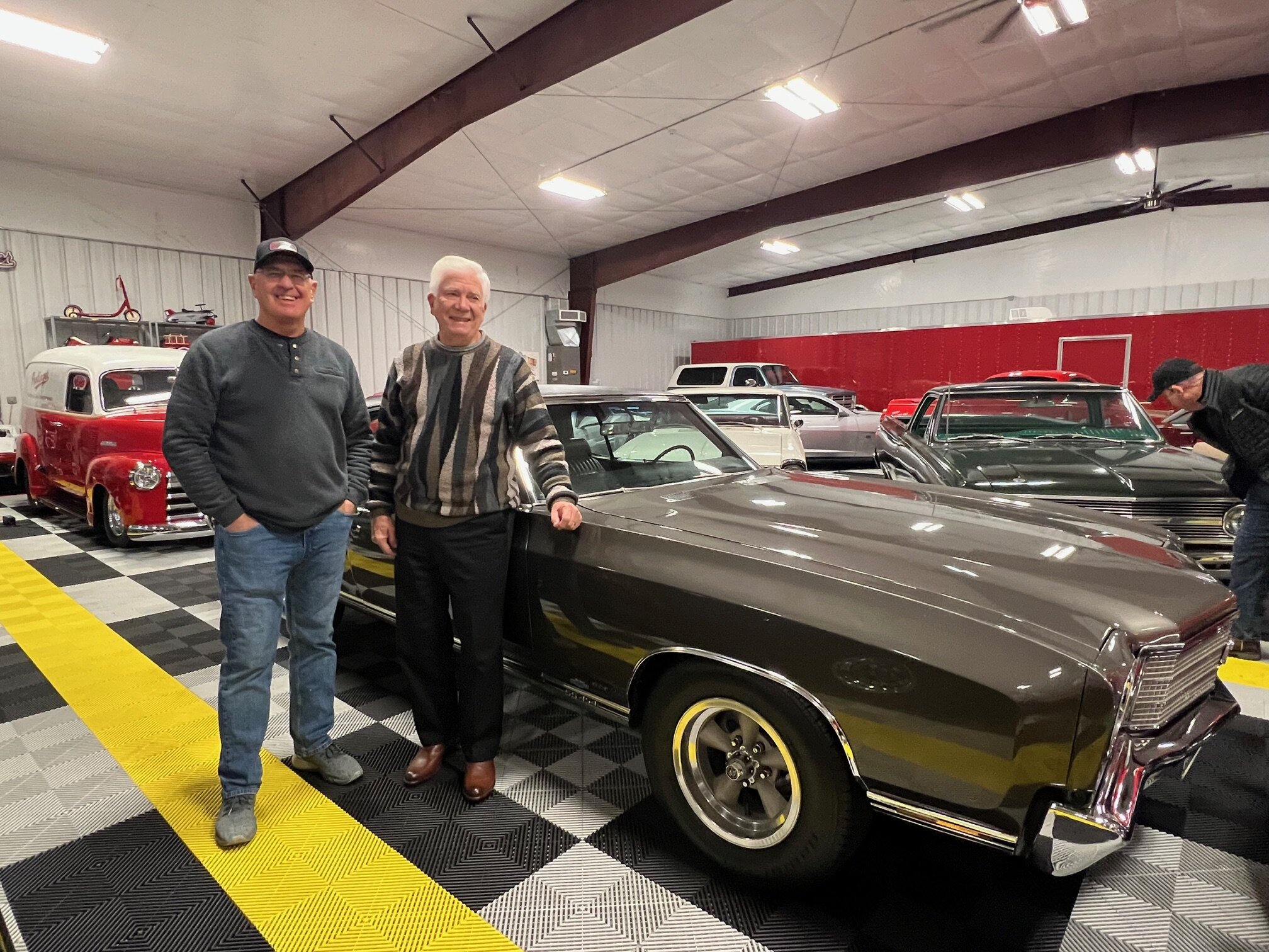
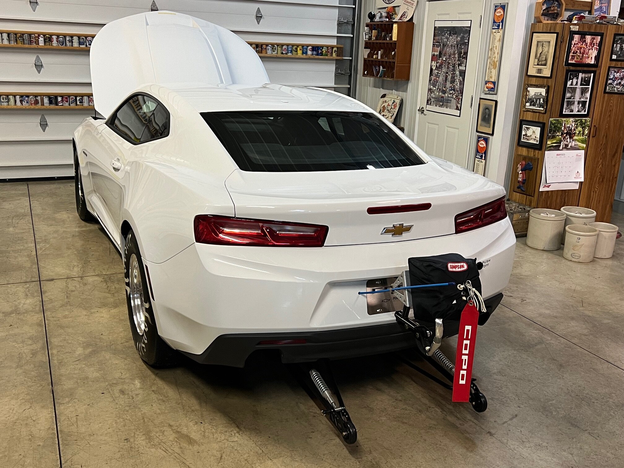
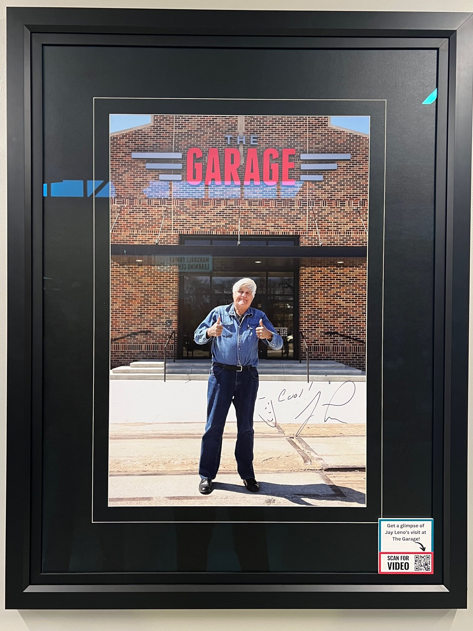
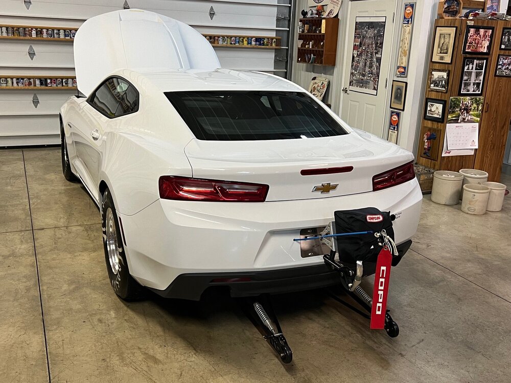
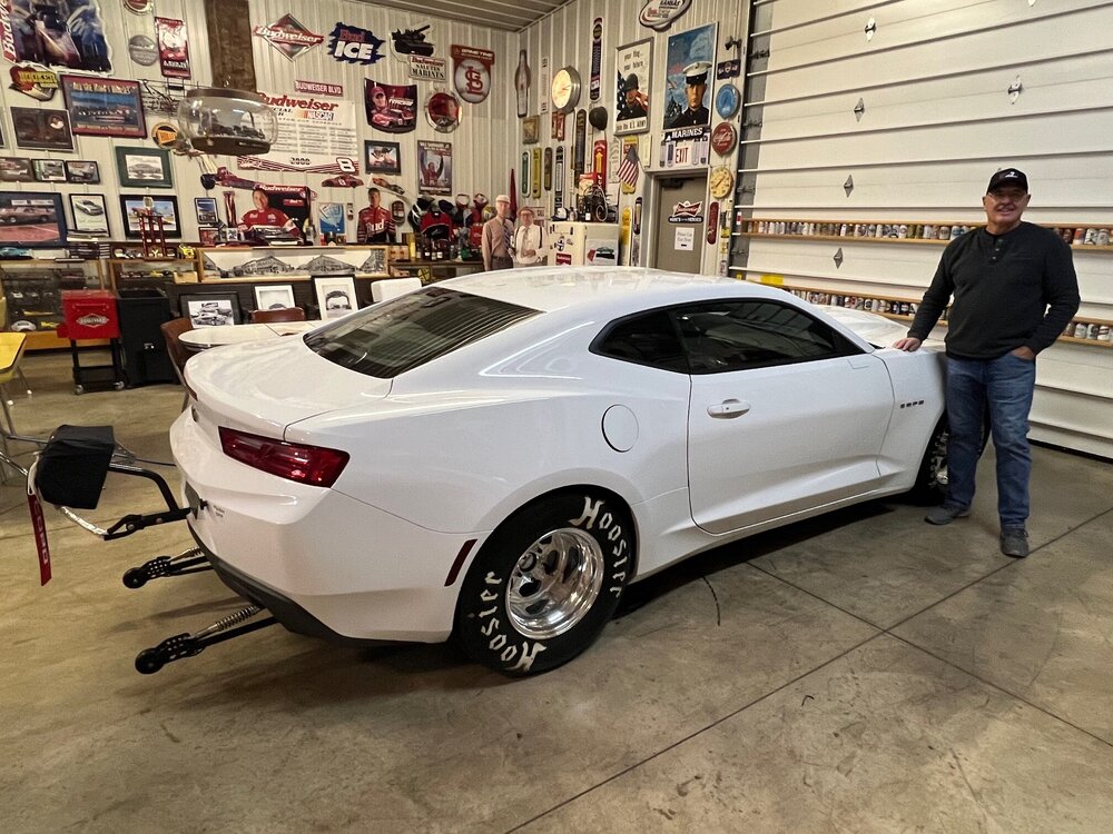
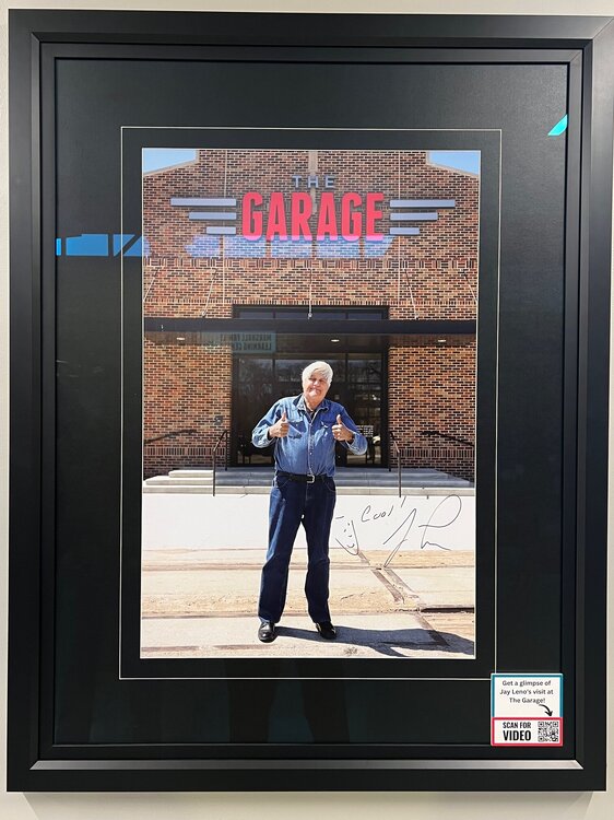
Yesterday I was fortunate enough to see (in person) the Dick Harrell-modified 1970 SS454 with an LS6 engine! It is beyond rare and in immaculate condition. Tim Pestinger, long-time owner of this one-off Monte Carlo, graciously hosted myself and my son-in-law in a private showing of this and many other incredible cars owned by himself and his brother, Tom. I was visiting my hometown, Salina, KS, yesterday afternoon and had arranged with my cousin, Greg, who is a friend of Tim, to see the rare Monte Carlo in his private collection. Much has already been written about this car and its history on this thread so I won’t repeat that, but it was really special to see it “in the flesh”! Tim actually drives his rare Monte on occasion and says it is a joy to drive – quiet, comfortable and fast! He has refused some outrageous cash offers and steadfastly maintains that it is not for sale. That’s understandable when you consider some of Tim’s other cars, like his white 2017 COPO Camaro (1 of 69 built) that is never driven and his Rally Green Nova Yenko clone that he personally rebuilt from the ground up to factory specs. Tim and two of his brothers each own a 2010 Camaro Hendrick Motorsports 25th Anniversary Edition by Callaway (number 9, 10 and 11 of 25 built). Tim and Tom Pestinger have also been greatly involved in the collaborative five-year project to create a new car museum in Salina known as The Garage. Jay Leno was present for its Grand Opening about a year and a half ago. Although they were technically closed while changing their quarterly feature section from Corvettes to convertibles, Tim got us in and gave us a private tour of that fascinating place. I think we can all be glad that one of the most unique first gen Montes ever created is in the good hands and care of Tim Pestinger. In the past, he has featured it in one of The Garage museum’s two large rotating display platforms so it’s getting more public exposure than just sitting in a private garage. Many thanks, Tim, for preserving and sharing your unique LS6 SS454 Monte Carlo!

- 43 replies
-
- 10
-

-
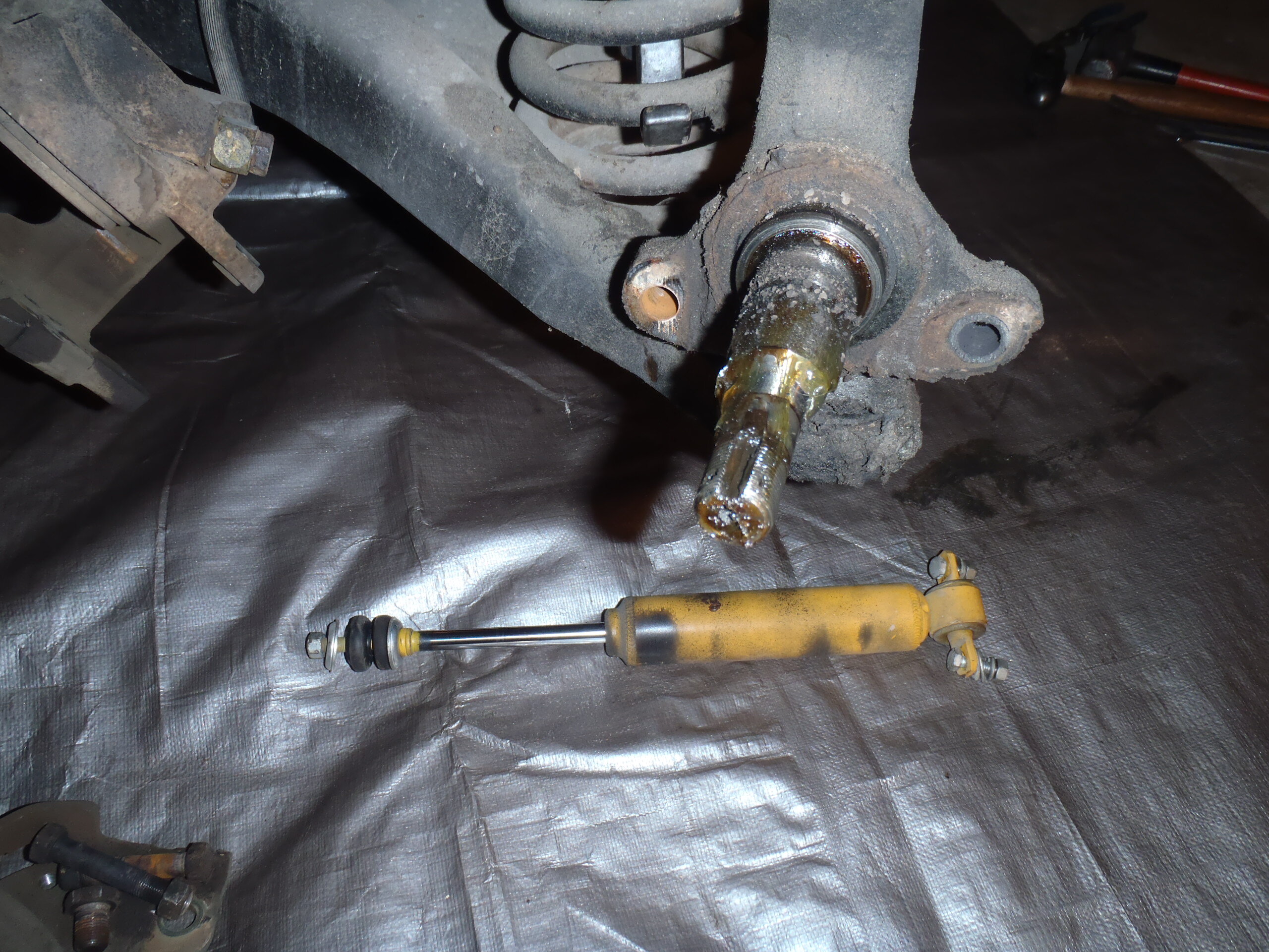
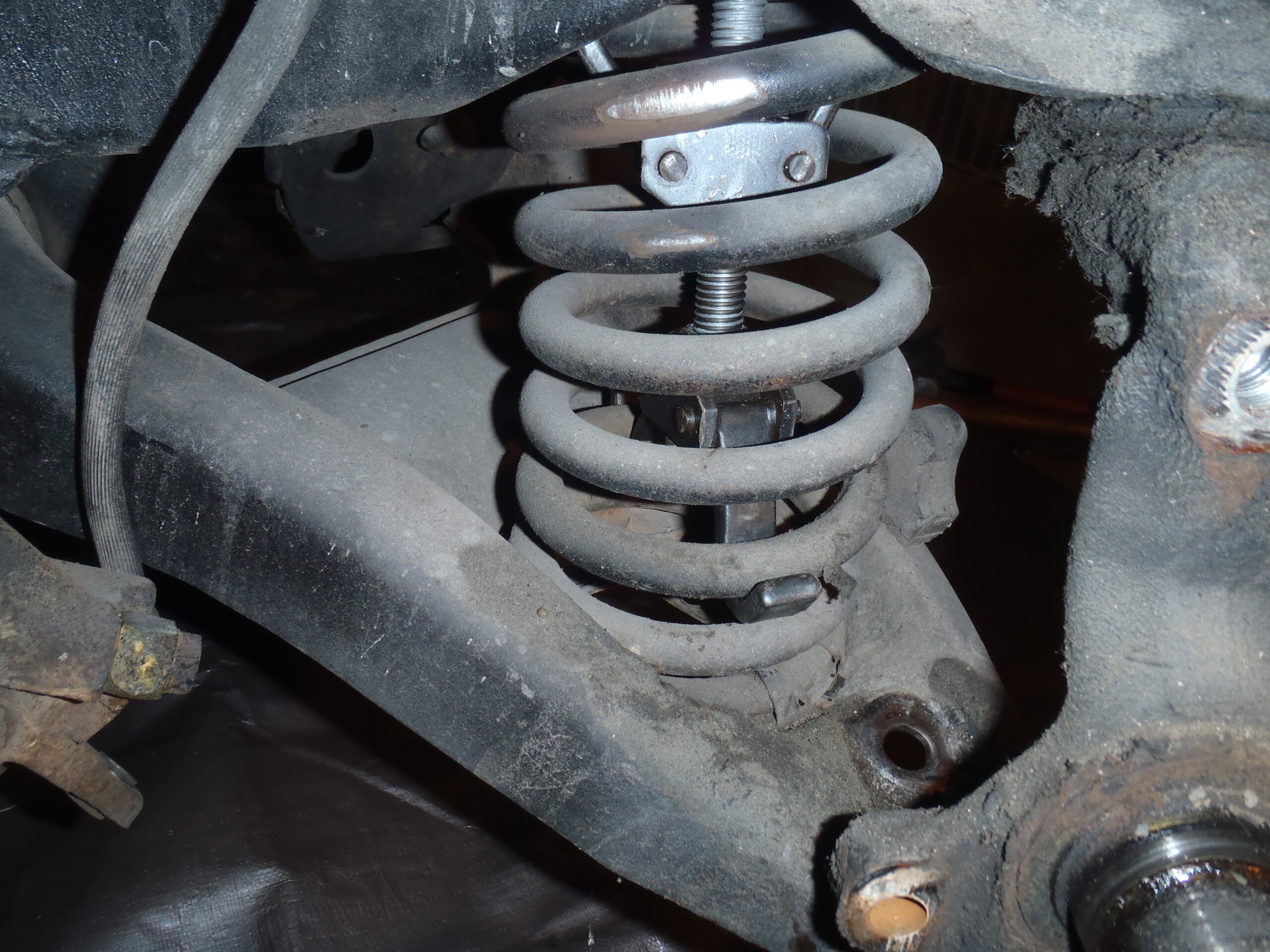
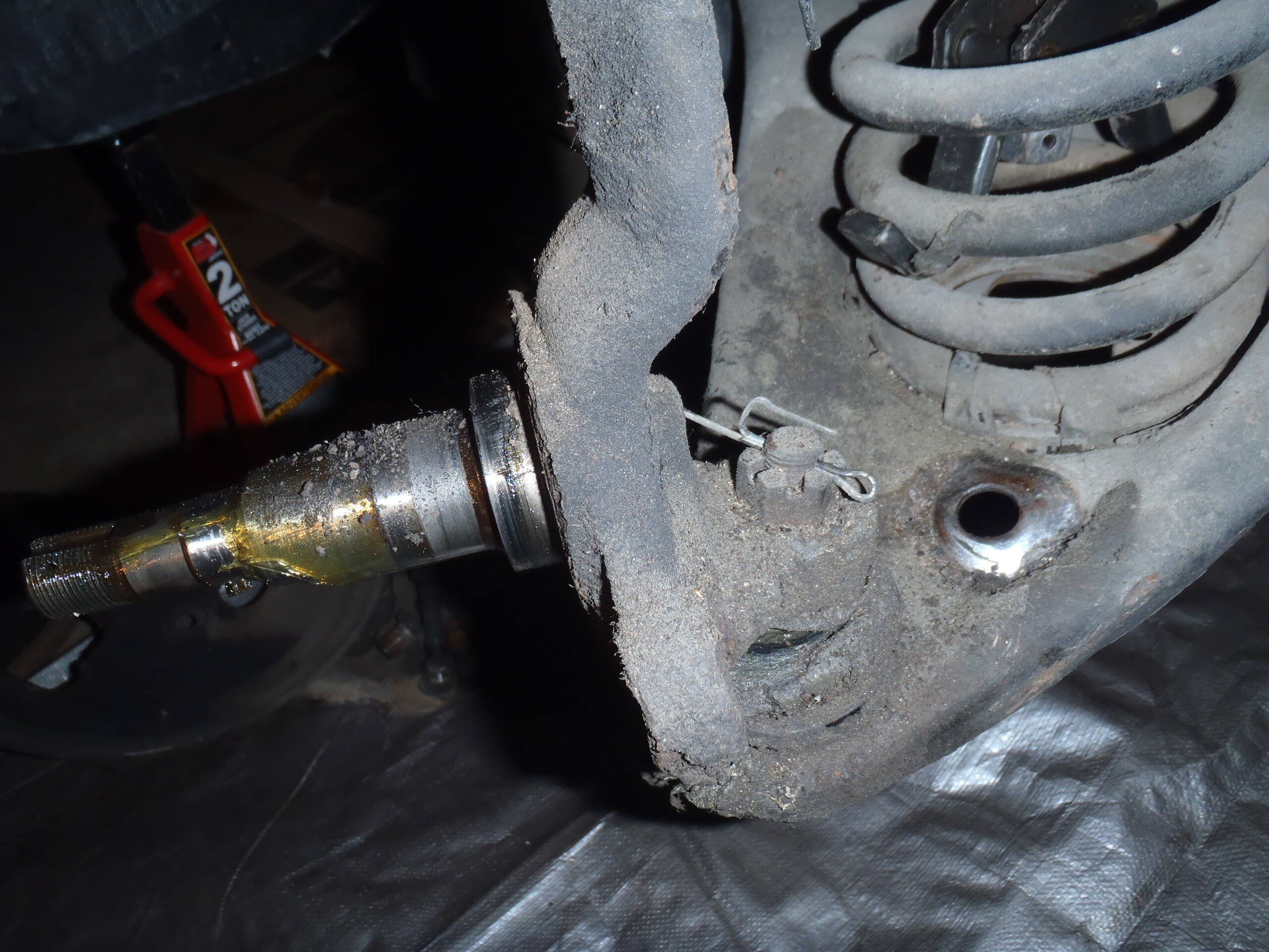
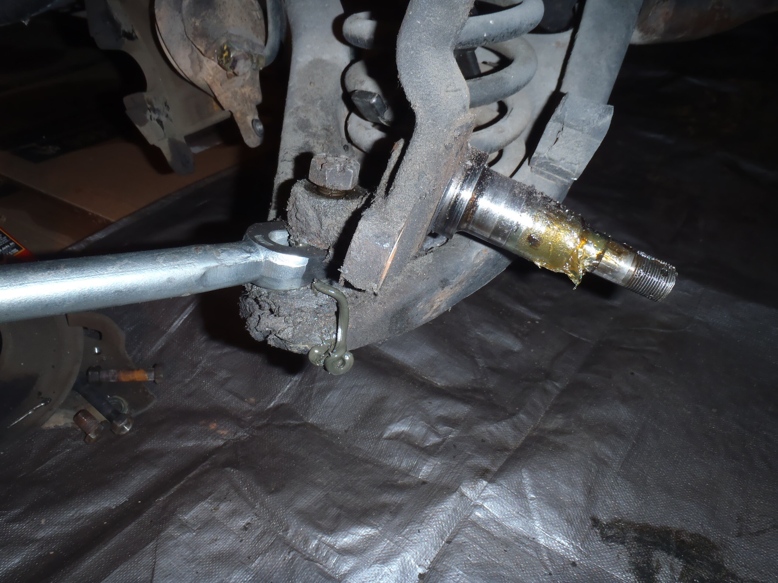
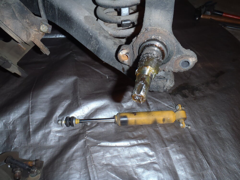
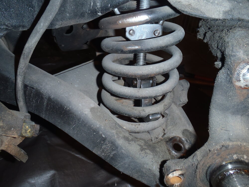
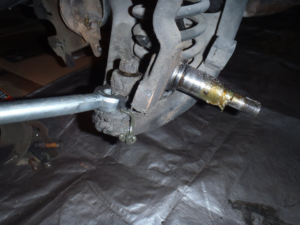
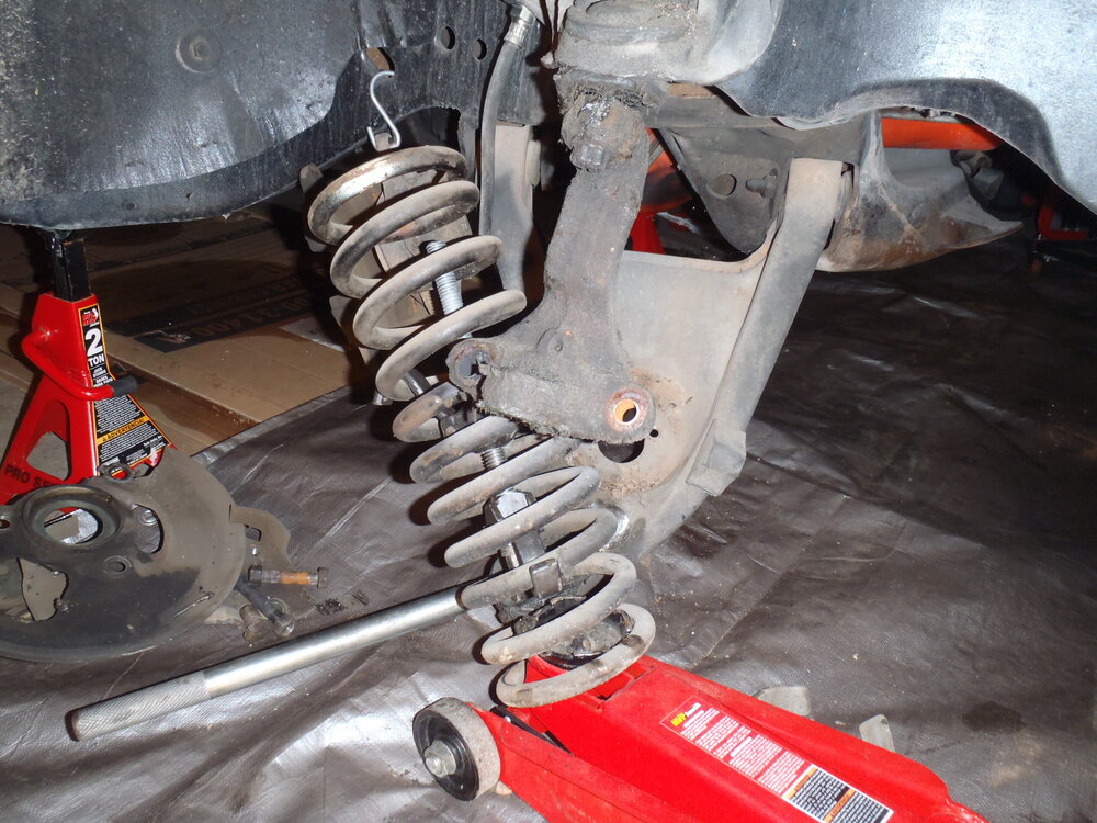
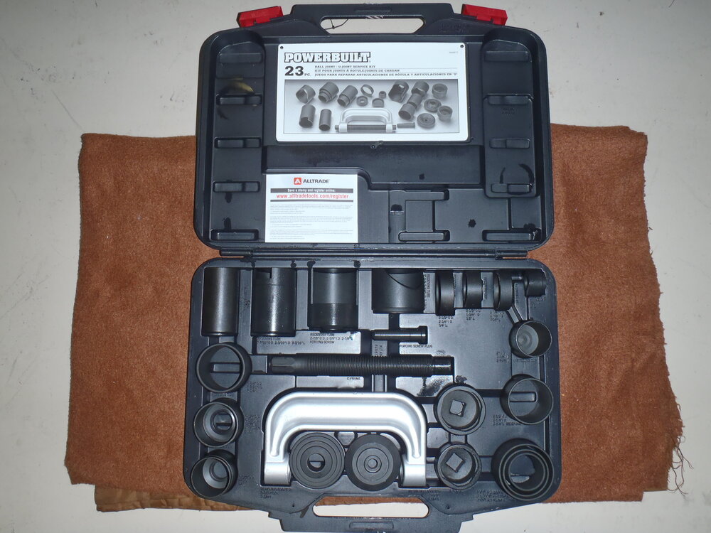
Wayne, you are wise to use some type of safety restraint for that job. The first time I did it, I pried the spring out of the lowered control arm socket and it still had enough compression to go bounding across the garage floor - fortunately I was not in its path. The next three times, I used an internal spring compressor! It's a bit of a Houdini exercise to get it positioned (after removing the shock, of course) but it can be done and is well worth the safety it affords (see photos). Good luck. Stay safe.

-
Juan, the 402 in my numbers matching '70 was highly modified before I bought it in 2010 and I have added some refining touches. It was bored .030'" over to 408 CI, decked .010", larger valves in '74 heads, Sig Erson 396 Hi Flow hydraulic cam and lifters, 11.9:1 TRW pistons, Torker II single plane intake, 750 cfm AED carb, Patriot 1 7/8" headers, 2 1/2" exhaust with turbo mufflers, Cloyes gear drive timimg, HEI distributor, Hayes clutch and pressure plate, Lakewood bell housing. The rest of the drivetrain is stock M20 4-speeed with Hurst Competition Plus shifter and a 3.31 posi. I've never raced it or had it on a dyno but I'm certain it's power potential is somewhat north of 400 hp which is more than I need for use as a daily driver. Due to its high compression, It requires the highest 93 octane gas generally available plus 108 octane booster and lead substitute. For 8 years, I simultaneously owned and drove a stock '70 SS454 which was a great cruiser with a 2.56:1 rear gear but my modified 402 would easily run circles around it. Your 402 is just an air pump. A balanced set of components to increase the air flow and deliver adequate fuel is all you need. I suggest you look for a 750 carb on a dual plane after market manifold, a mild performance hydraulic cam (roller or tappet) and a set of tube headers mated with a free flowing exhaust system. If you are going to completely rebuild, over-boring and higher compression pistons would be next but I do NOT recommend a compression ratio greater than the 10.25:1 the factory used in '70! JMO Good luck!
-
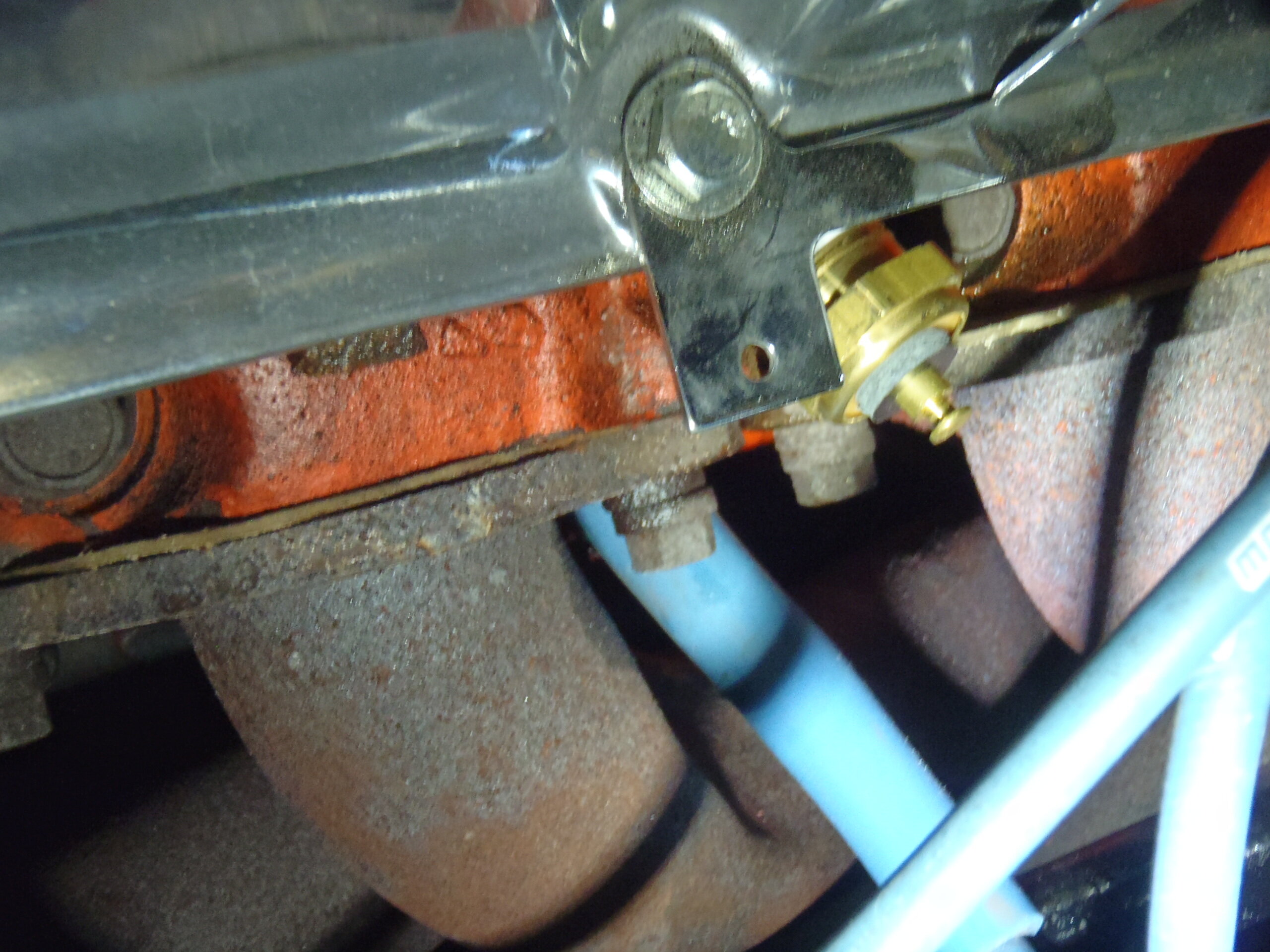
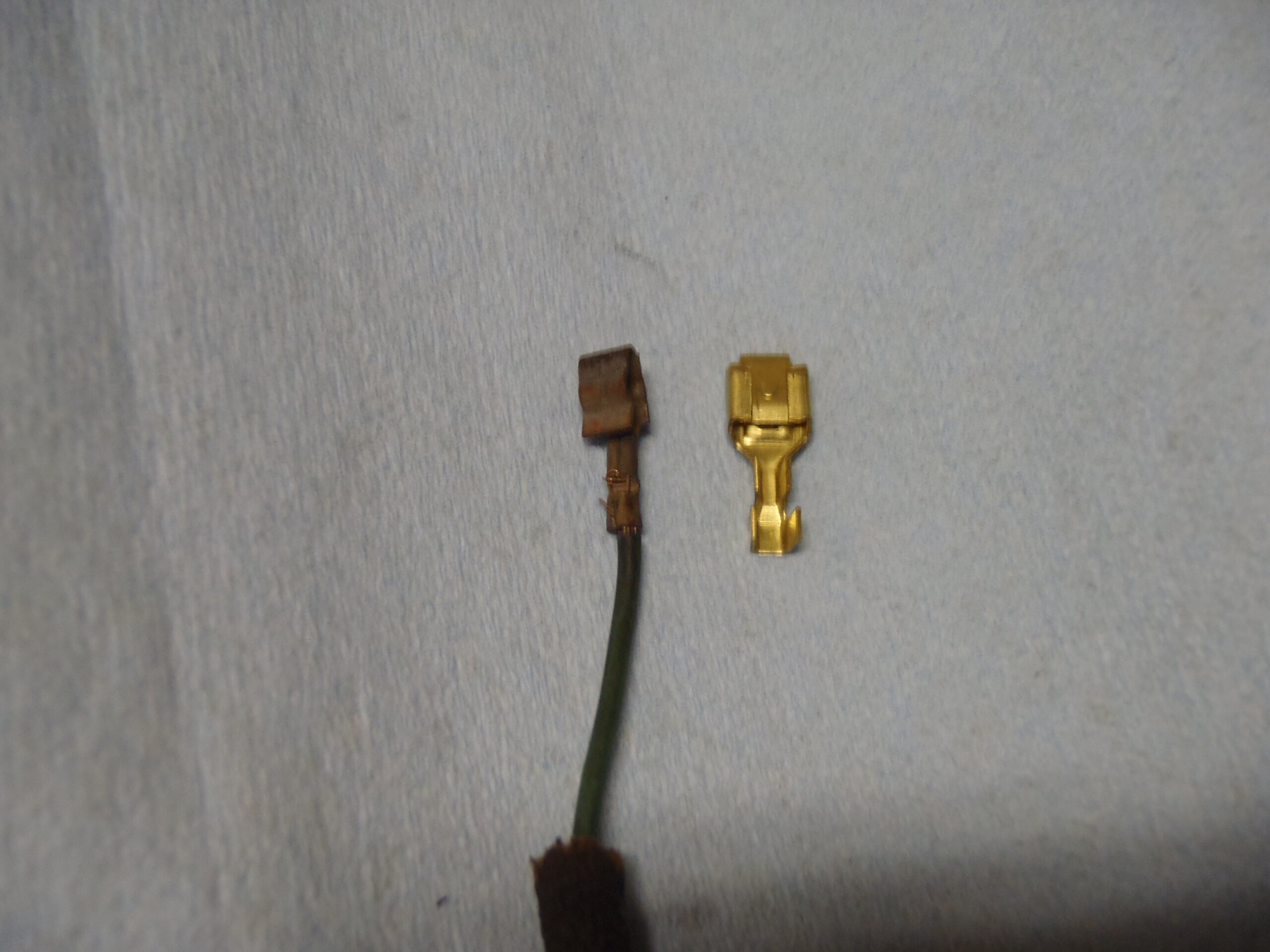
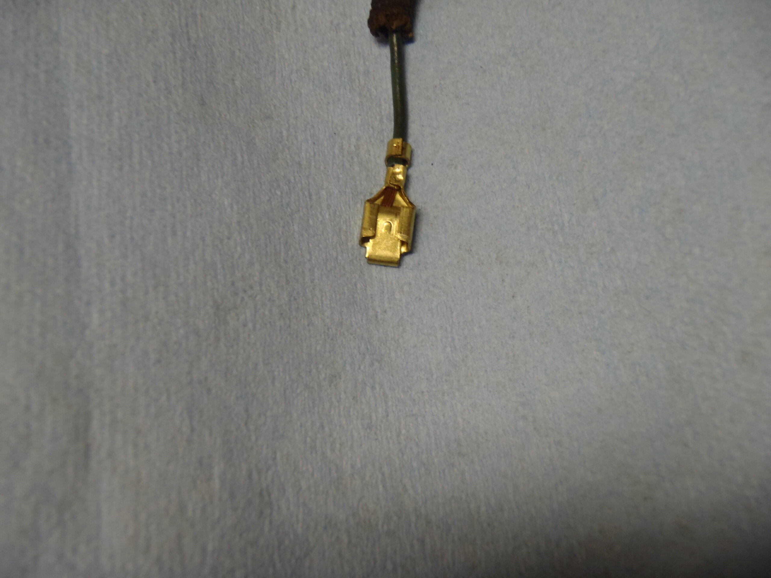
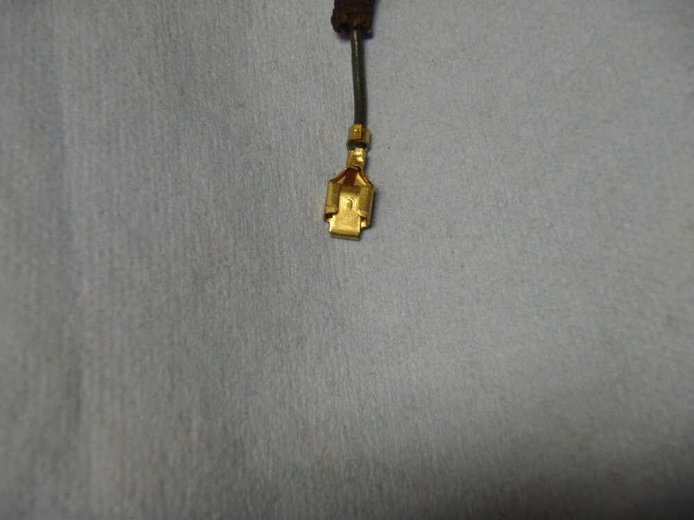
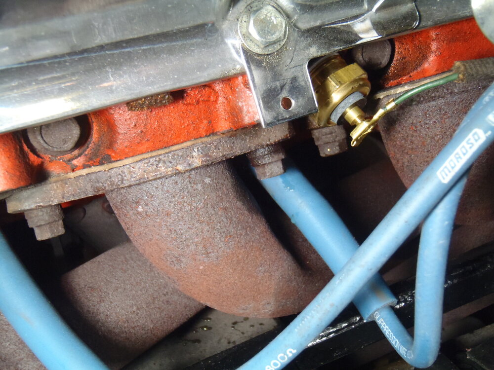
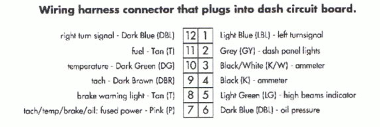
Greg, there's obviously something wrong with that circuit but it might or might not be the sending unit. The new gauge seems to be getting both power and a signal so it is logical to suspect the sending unit. There was one important change in the wiring of that circuit and that was to move the dark green wire from position 9 to position 10 in the dash harness plug that goes to the PC board. I assume you did that but you may want to check. The signal strength should only vary gradually with the water temperature. Since the gauge is jumping around, I suspect it is a connection/continuity issue. The instructions call for replacing the factory sending unit on the passenger side with the new sensor, so I assume that is what you did. I actually did not follow that instruction and mounted the new sensor/sending unit on the driver's side of the block just above the exhaust port (see first photo). I left the original sending unit in place and just disconnected it. I don't remember if I sent you my enhanced instructions for installing that sonnie24 kit, but I wll paste in here the section about installing the new temperature sensor/sending unit: Replace the engine temperature sending unit: 1. The new temperature gauge required a different sending unit which is included in the kit. 2. Locate the current temperature sending unit in the driver’s side cylinder head just above the #3 spark plug. 3. Disconnect the dark green (temperature) wire from the sending unit and leave it lay for now. 4. Use a 24 mm deep socket to unscrew the old temperature sending unit from the cylinder head. CAUTION: There is coolant present in the cylinder head that will pour out when you remove the sending unit so have the new one ready to insert immediately (Teflon tape already on the threads) and a rag to catch some spilled coolant. 5. Immediately insert the new sending unit and tighten it securely to prevent leaking. 6. Clip the old connector off the end of the dark green (temperature) wire, strip back a bit of insulation and crimp on the new style connector that is supplied in the kit. (see second and third photos) 7. Connect the dark green (temperature) wire to the new temperature sending unit. 8. All wiring for this project should now be complete. Also, I assume you changed the connector on the end of the dark green wire as stated in #6 above. If so, be sure you have properly crimped the new connector onto the dark green wire. The only other thing I can think to check is to be sure the new connector is firmly seated on the stud of the new sending unit (see last photo). Regarding checking to see if the new sending unit is working, I suspect it is putting out a very low voltage analog signal. When the engine is cold, I would not expect to see any millivolts between the connection stud and a good ground. With the engine warm/hot, I would expect to see a positive millivolt reading. If you don't get a reading with a warm engine, I would suspect the new sending unit is bad. But, again, the fact that your new gauge swings wildly suggests a circuit problem so I would definitely check all connections and the end-to-end continuity on the darkgreen wire at their respective connectors. Good luck.


-
The arm of the Z bar is also slightly twisted and the rod is attached on the outboard side, lower hole on my '70. I can't get under there to check but I wonder if the rod is more perpendicular to the clutch fork arm when the clutch is depressed (if the rod is on the outboard side)? In any case, mine seems to work fine installed as the Assembly Manual shows.
-
Yellow does look nice .... on bananas!
-
Great story and photos, Bruce! Grandchildren are a real blessing but they grow up too fast! Unfortunately, none of mine have shown any interest in driving my 4 speed Monte. ☹️ We're working on great grandchildren now - two already and one on the way.
-
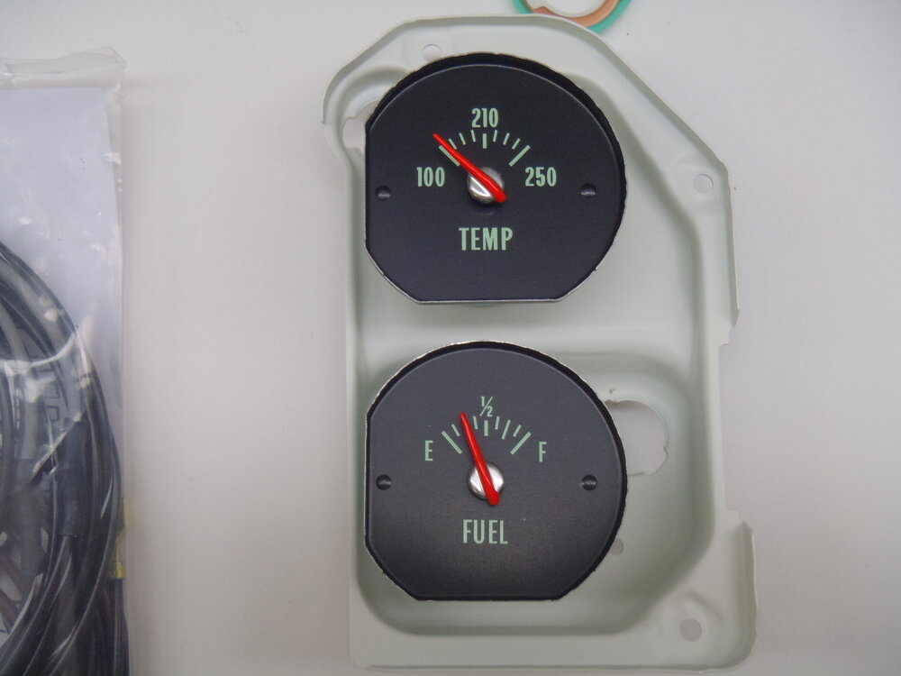
Dave, I would still do all of the steps I listed originally. If you confirm at all of your connections for power and signal are good and that each of the power and signal paths have continuity, then I would reasonably conclude the gauges have been damaged. The fact that everything else that uses the new printed circuit is working also points to the possibility of gauge failure. I don't know any better way to test the gauges than to put them into a system that has everything esle working, especially if you have confirmed that everything the gauges need to function properly is operational. If you need new gauges, I suggest you contact sonnie24 on eBay as he provides those exact gauges in his full gauge dash conversion kits. Be sure to specify '70 gauges to get the green tinted numerals and gauge markings.
-
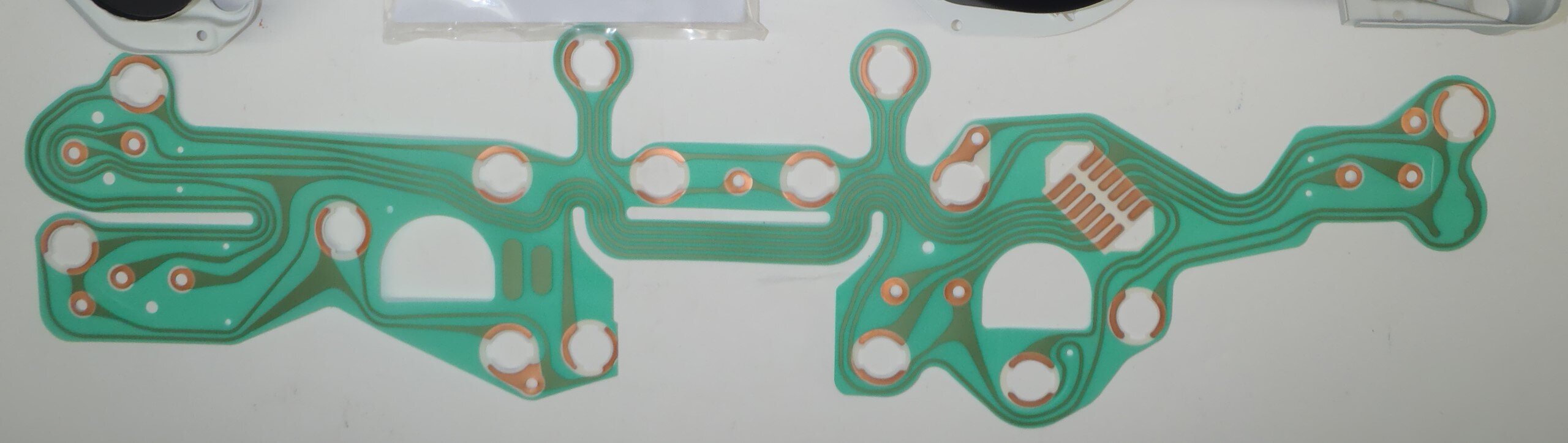
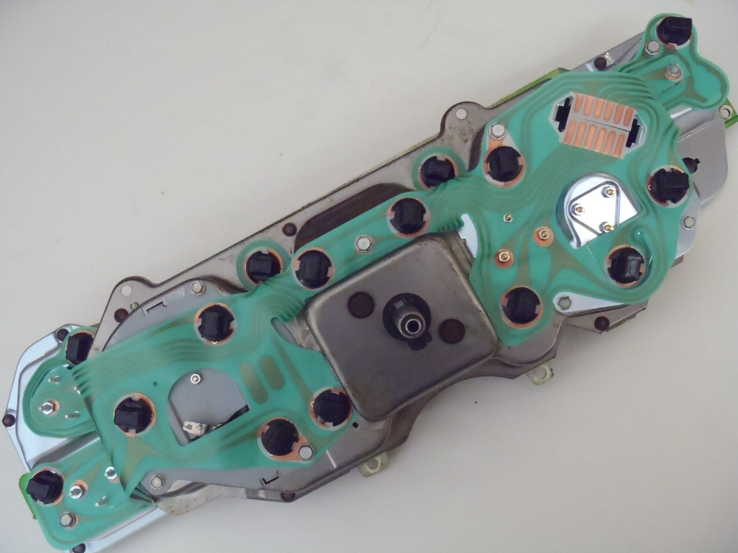
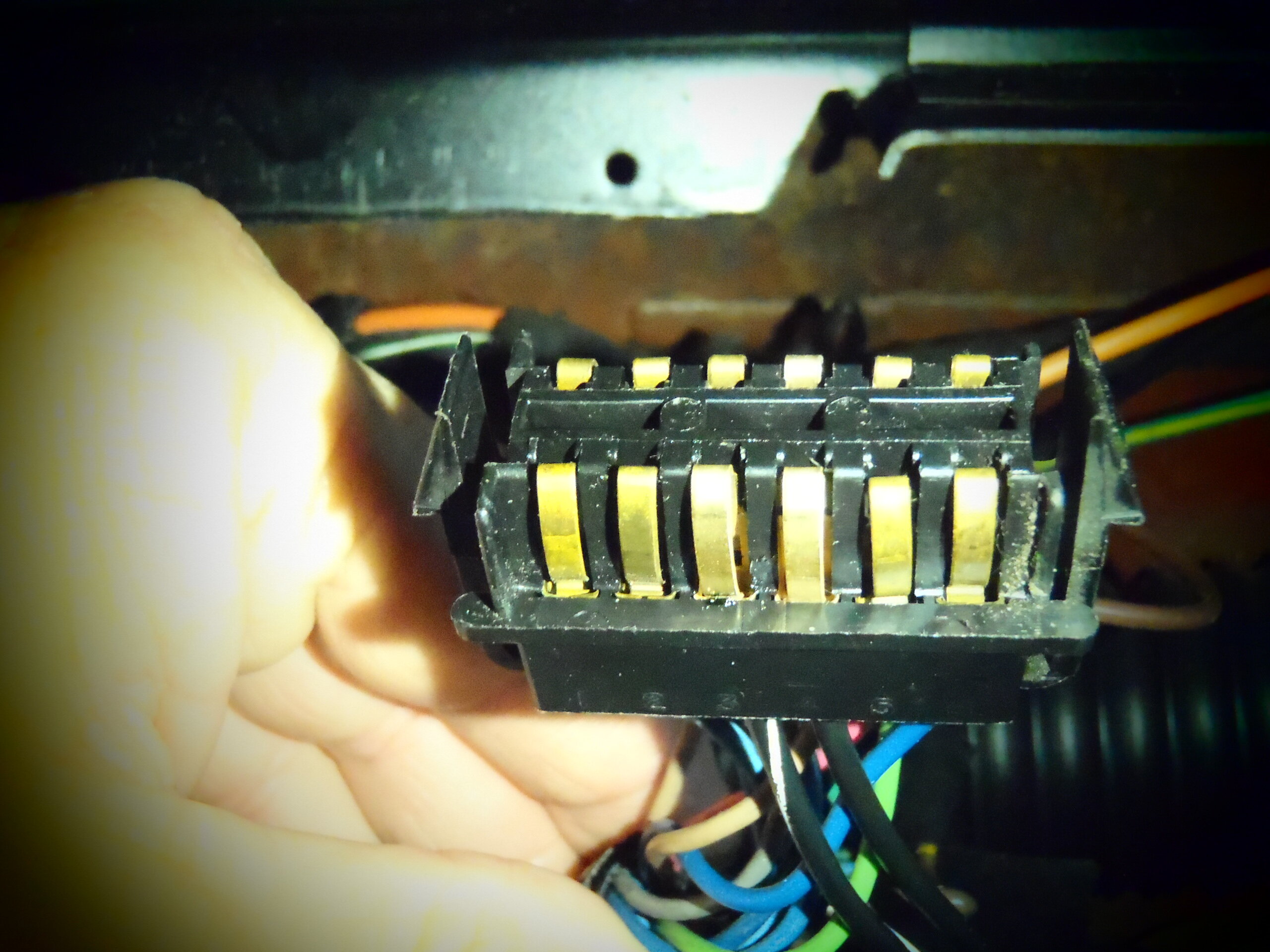
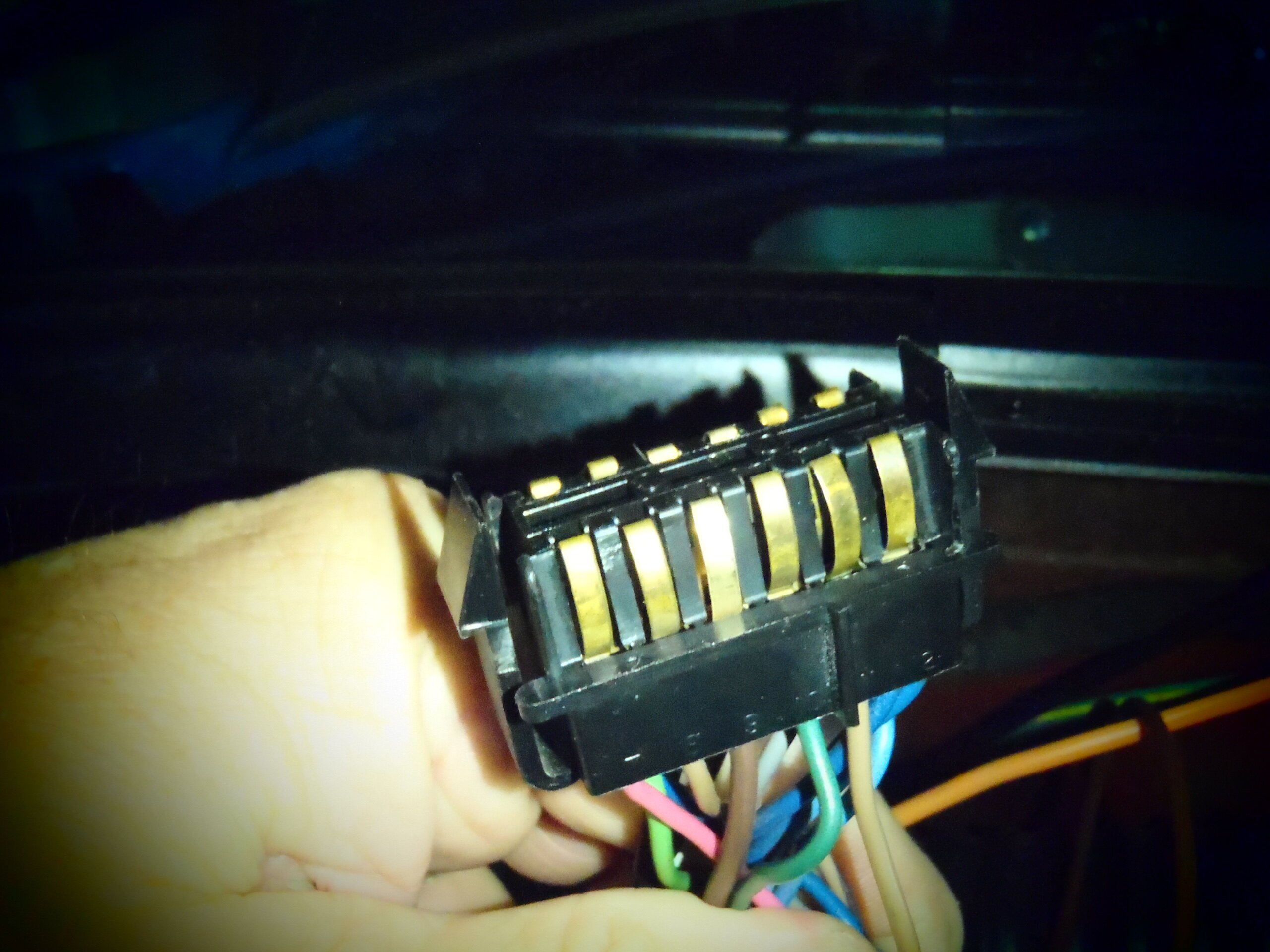
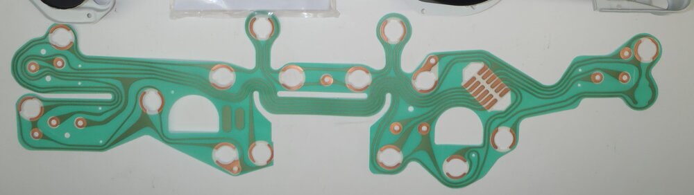
Dave, I will attempt to help troubleshoot and fix your printed circuit replacement problem but the only way I know to approach this is to ask some basic questions, take a close look at the factory full gauge printed circuit, and do some continuity testing. First, what was the reason you replaced the printed circuit? What was and wasn’t working properly? Second, did the new printed circuit fix the original problem(s) and/or create new problems? In post-replacement testing, what functioned properly and what didn’t (I know you have already said the Temp and Fuel gauges aren’t working)? If things that were originally failing were not fixed with the new printed circuit, their root cause may well be upstream in the instrument cluster plug, wiring harness, fuse panel or other connections. Answers to the above questions are extremely important to pinpointing the possible problem(s). For example, if your dash lights, turn signals and tach are all working, you do not have a grounding issue as they all require a good ground through the printed circuit. The printed circuit has fourteen serpentine, copper ribbon conducting paths (as a careful examination will show). Twelve of them begin at the instrument cluster plug socket and two of them are grounded directly to the metal instrument cluster housing with three attachment screws (be sure they are snug). Those fourteen paths provide 12V DC power or modulated electric signals to the low-wattage lights and analog gauges in the instrument cluster. NOTE: The CLOCK is completely independent of the printed circuit as it has its own power wire and needs no signal wire. Also, the factory AMMETER IS powered through the printed circuit (positions #3 and #4 of the instrument cluster plug) as it simply measures the current flowing through the 12V system. When you look at the factory printed circuit from the front (facing rearward), the instrument cluster plug socket is numbered as follows: Upper right tab is #1 and then consecutively down to #6 at the lower right. Switching to the left bank, the lower tab is #7 and then consecutively up to #12 at the upper left. NOTE: For now, I am assuming that your replacement printed circuit is not damaged and that all circuit paths are functional. However, it may be necessary to confirm the integrity of individual power/signal connections/paths with a DC continuity tester or multimeter. Since both the Temperature and Fuel gauges are 12V analog instruments that convert a modulated electrical signal to a mechanical indicator needle, they both require connection to a 12V power circuit and an individual signal circuit. They both get their power from the #7 path which is fused in the fuse panel on the inside firewall (the fuse should be good if other gauges/lights are working). The Temp gauge gets its signal from the #10 path and the Fuel gauge gets its signal from the #11 path. Note that the #7 path also provides fused power to other devices (i.e. tach, brake warning light, oil pressure light) so, if any of those are currently functioning correctly, you possibly do not have either a power supply or a grounding problem with your Temp and Fuel gauges. HOWEVER, the right-hand stud of those gauges might not firmly attached and in contact with the printed circuit. Be sure to check both connection and path continuity between the right-hand stud and the #7 tab in the cluster plug socket for each of those gauges. If both gauges are getting power, the gauge failure must be lack of signal. Since you already told us that those gauges were functioning properly before you did the replacement, the missing signal problem must be in the printed circuit or its connection at the instrument cluster plug. I suggest you carefully examine and thoroughly clean the #10 and #11 contacts in both the plug and the respective tabs on the printed circuit. Be sure the springy contacts in the plug are not damaged or dirty and are making good contact with their respective printed circuit tabs when the plug is in place. The last thing I know to check are the connections at the left-hand stud of each gauge to be sure they are snuggly contacting the printed circuit. Also check the connection and path continuity for each gauge between the left-hand stud and the #10 or #11 tab, respectively. Obviously, if you find any continuity issues in the replacement printed circuit, it will have to be repaired (not easy to do) or replaced. Sorry this got so long – someone may have a quicker, easier method to troubleshoot your problems. Good luck!


-
It sounds like you are simply replacing the printed circuit on an original full gauge dash instead of doing a conversion from a non-gauge dash? Do your dash lights function properly? If so, the issue has to be a connection or continuity problem as addressed above if some gauges are also working since they all use a common ground. I agree with the suggestion to check the main plug followed by the individual circuits and their connections at the gauge studs. Of all the many repairs and upgrades I've done on my Montes, working on the instrument cluster has been the most frustrating - I hate it! Good luck!
-
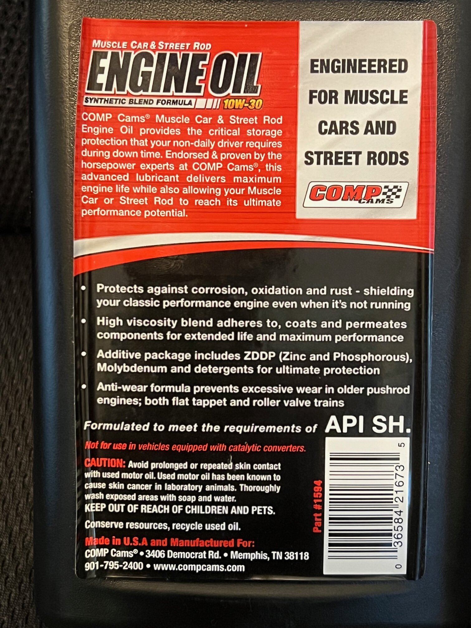
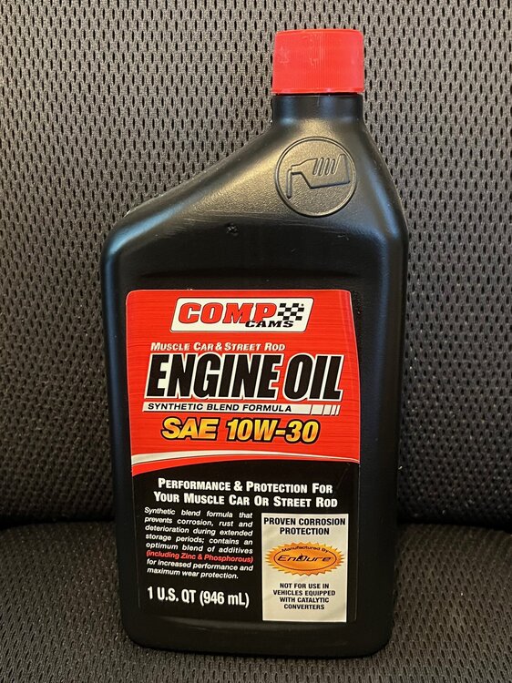
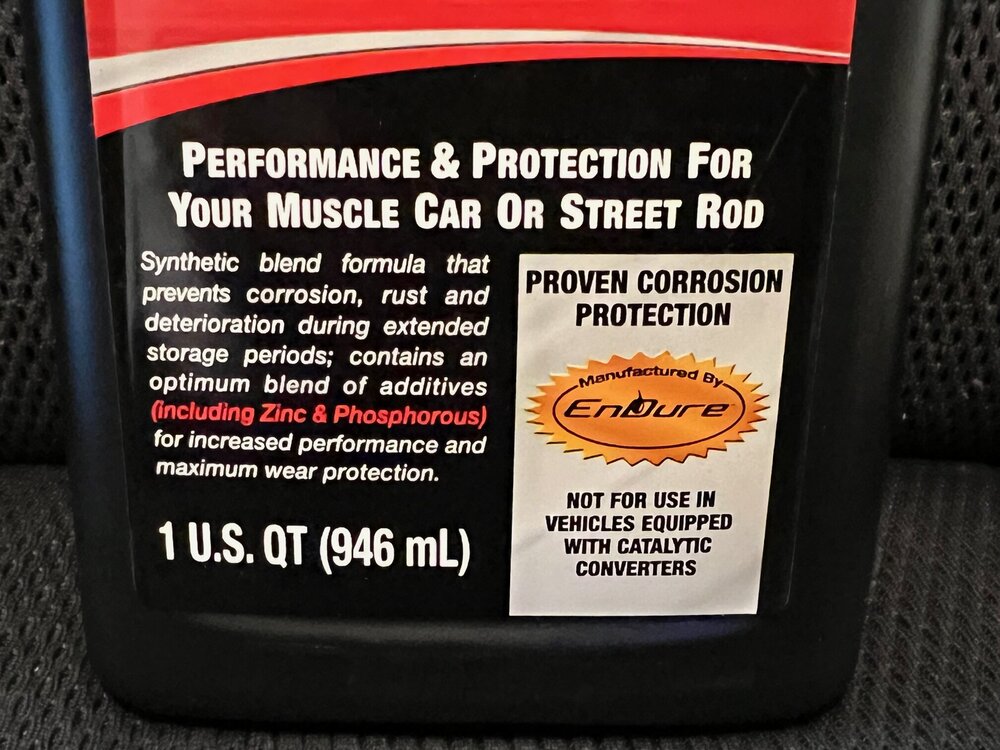
Just looking for feedback on a particular engine oil if anyone has experience good or bad. At a Veteran's Day car show today, I picked up a 12-quart case of Comp Cams Synthetic Blend 10W-30 Engine Oil for a great price. The seller had a '66 GTO with a built 461 ci Pontiac motor. His engine builder advised him to go with the Comp Cams 15W-50 blend instead due to tolerances used in that build. He also races the car frequently, so that is understandable. I am intrigued by the fact that this product contains zinc, phosphorous, molybdenum and detergent additives and is formulated specifically for older muscle cars or street rods. My 408 BBC was also built (way back in '74) but not to racing tolerances or specs. It has a Sig Erson 396 Hi-Flow hydraulic cam and TRW 11.9:1 forged pistons but it never sees high revs so I doubt I need to continue using 20W-50 oil plus zinc additives. This motor has over 40K miles on it since rebuild and does not smoke or use oil excessively at all. Just wondering if anyone has personal experience with this particular brand, weight and blend in their first gen Monte or other muscle cars? Thanks.

- 1 reply
-
- 3
-
-
Welcome to the club and forums, Mark! Your triple black '72 is definitely a looker - nice job on the restoration! I see you are in Ft Myers so I am just up I-75 (or US 41) from you in Punta Gorda. I just got back yesterday for the winter season so I'll be out and about with my '70 starting today. Maybe we can hook up at one of the many car shows held in the area throughout the winter. It would be great to meet you and see your beautiful '72 in person. PM me if you are interested. Thanks.
-
Welcome to the club and forums, Bill! That's an interesting way to get your "SS454 Monte itch" scratched but if you've got the time, skills and resources you can restore it to it's original glory. It won't take a lot to make it look better, but it will take lots more to make it look great! That is truly a heavily optioned car so you've got a lot to work with. My '70 was built in Baltimore and I found a build sheet inside the front passenger seat, hog-ring stapled to the seat springs. Hope you are able to find one or more in your car. Enjoy the club and your new SS!
-
Ummmm ..... no thank you very much!
-
Gorgeous '72, Kevin! Congratulations on your show wins! Love the color combo, stance and blackout grill!
-
Congratulations and welcome to the club, Jim! You own a rare big block, factory 4-speed, '70!! Have you had her awhile or is this a recent acquisition? Hope it is still matching numbers, but even if not it should be a blast to drive! Looks like someone has done a reasonably good job integrating a cowl induction into the Monte hood and the Chevelle rally stripes appear to be nicely done, also. I imagine you are planning to provide the necessary love to bring this rare survivor back to prime condition. That original drivetrain alone will make it well worth some serious restoration! In the meantime, enjoy driving her! Where was your '70 built (the 7th position of the VIN is the assembly plant code)? If the code is anything other than an "F" (Flint), you might be able to find a Build Sheet somewhere in the seats or under the gas tank. The hand-written list of optional equipment on the Bill of Sale is really hard to read but I don't see power steering on there. My factory 4-speed '70 was originally built without power steering, also, and it was a beast to parallel park or turn around until I installed a salvaged factory power steering system. Thanks for the pics. Enjoy the club!
-
New Monte Owner has questions. Suspension, lights, etc....
MCfan replied to BYBIS's topic in General 70-72 Monte Carlo Forum
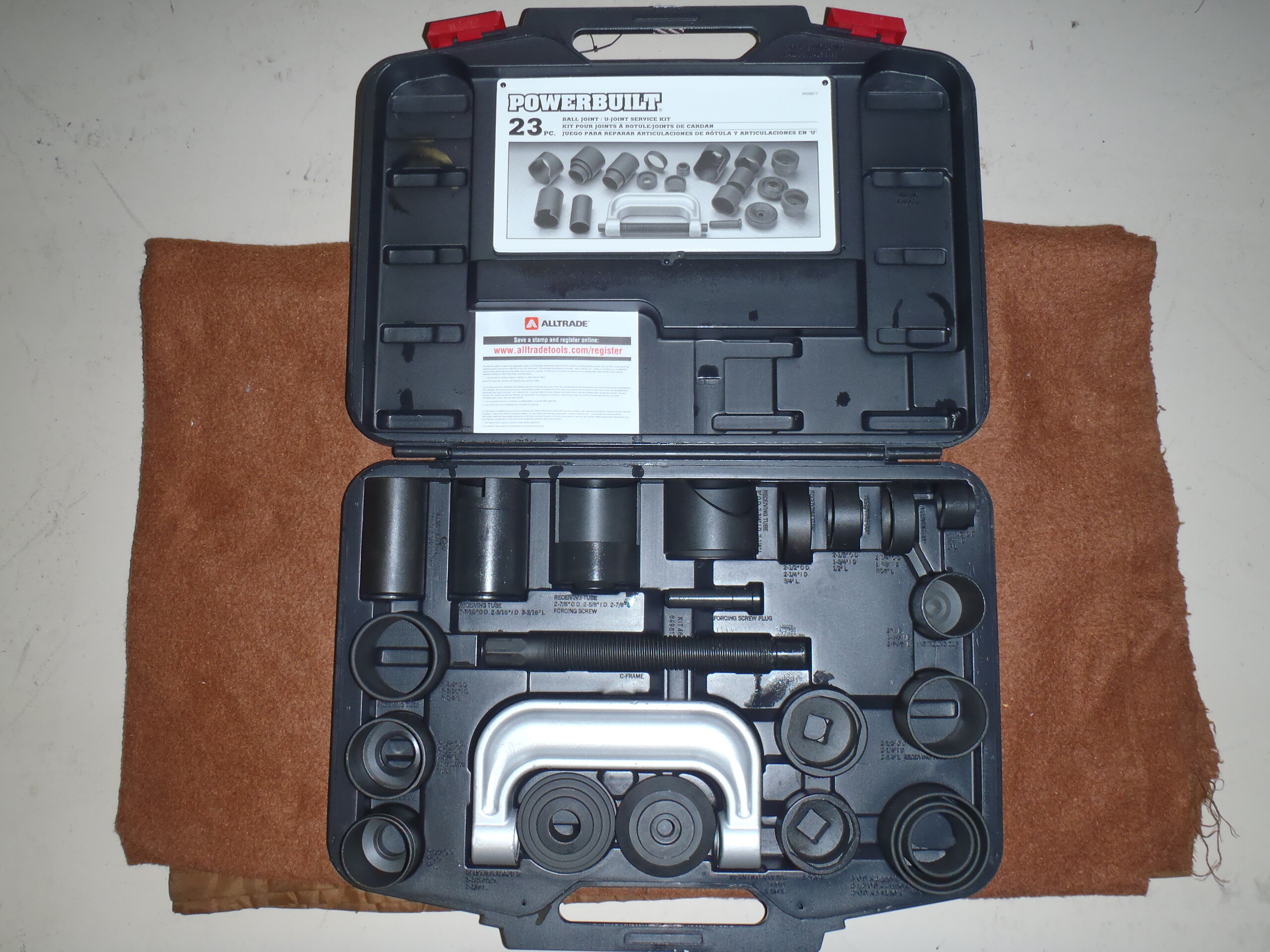
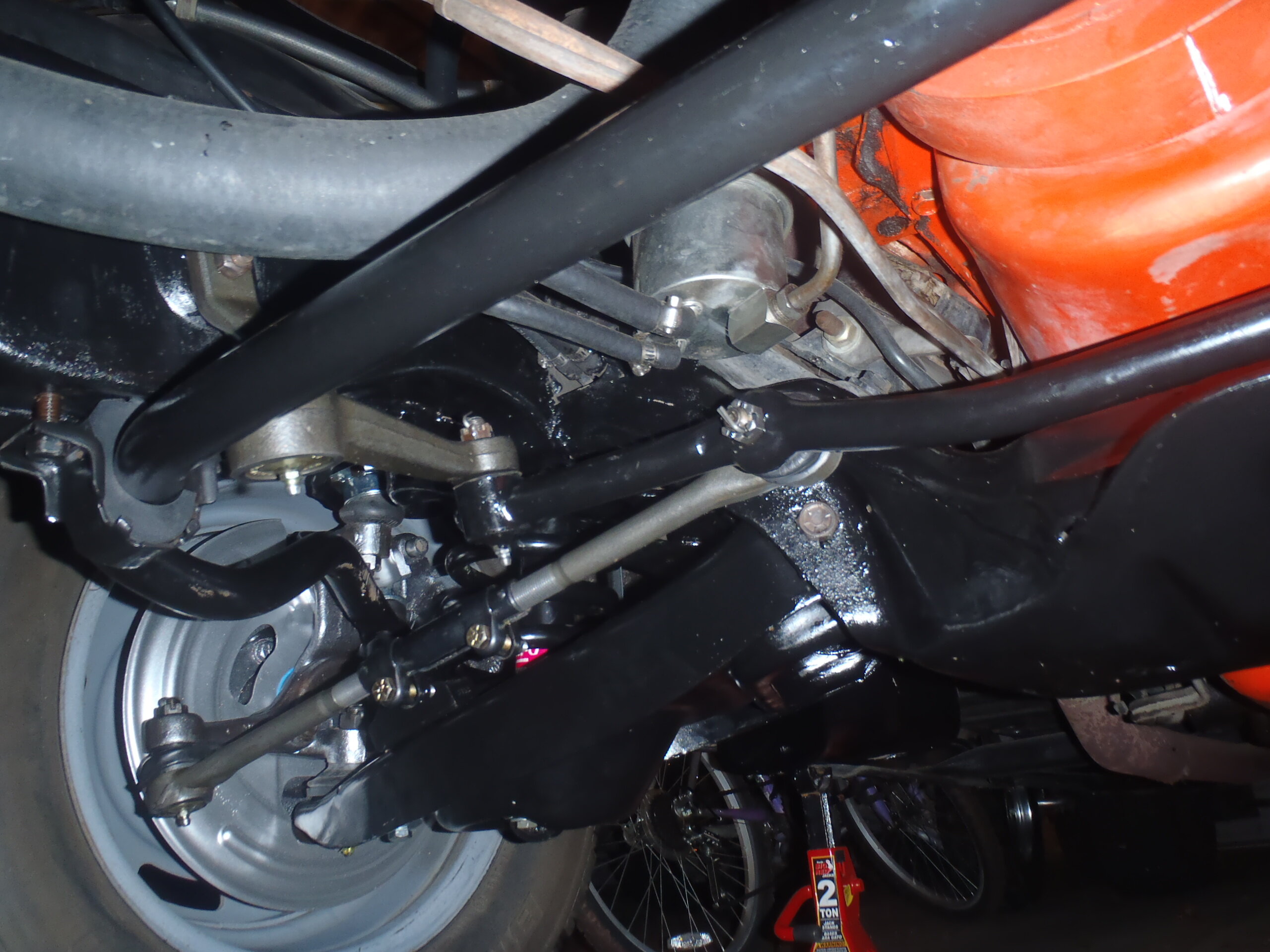
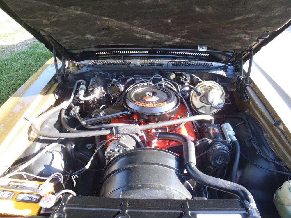
Well, Thomas, now that you finally have your 53 year old SS, it's time for the discovery, repair and personalization fun to begin! 😄 I bought my '70 SS sight unseen (except for a few photos of the exterior by the prior owner) so I was confronted with a ton of surprises when I got it home! But, that's somewhat to be expected and all a part of the joy of owning a classic car. Like many of our members here, I have done a lot of mechanical repair/replacement/upgrade projects across the two '70s I have owned. For one thing, I completely rebuilt the front suspension of both cars including wheel bearings, disc brakes, ball joints, control arm bushings, tie rod ends, sway bar bushings, idler arm joints, shocks, coil springs as well as stripping and repainting every part that was reused. I also installed a used factory power steering system and rebuilt the pump prior to installation. Both projects made a significant difference in how the car handled. At one time, I had extensive photo project journals available on PhotoBucket but then those jerks started charging hosting fees which I refused to pay so they dumped me and all of my content. Fortunately, I still have all of the photos (just lost the information/instruction in the captions) so I might be able to share something helpful if you keep telling us what you need. On the first frontend rebuild, I ordered a suspension rebuild kit (from eBay, I think) which had new parts made in India. They seemed to be of reasonable quality and have worked well so far. The second time, when I rebuilt the front suspension on my '70 SS, I decided I wanted all US-made parts so I ordered all of the components separately and went with the Moog brand whenever possible. There wasn't a huge price difference as I recall. Don't know if you've done front suspension rebuilds before, but I hadn't. Replacing front coil springs requires some care and the proper tools if you want to stay safe. IMO, a good pair of internal spring compressors are essential for the job. Maybe you already have some. If you don't already own a ball joint and control arm bushing replacement tool set, rent or borrow one from your favorite auto parts store - you'll be glad you did. The Moog 6330 coil spring is a popular replacement for the factory "GQ" code spring used in most '70 SS builds. I certainly would not go with anything lighter, especially since you have AC adding weight to the front suspension. Also, remember that the front sway bar on an SS is 1 1/8" diameter so don't buy the standard 7/8" diameter rubber bushings. The larger ones can be hard to find. I attached a photo of the engine compartment of my former SS with AC (but prior to replacing the missing load level compressor). Let the fun begin ...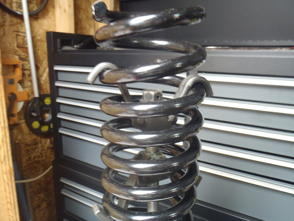

-
Congratulations, Thomas! Once you get the Super Sport itch, it eventually has to be scratched! Enjoy!
-
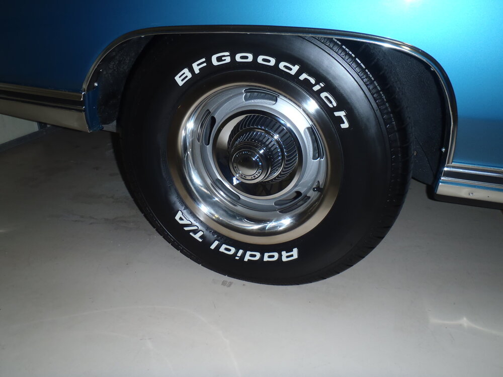
Thomas, your stock rallys are 15x7" with a .30" (+8mm) offset which translates to a 4.30" backspace. You can safely mount up to a 255/60-15 on those rims. That tire is 27" tall and 10" tread width. Anything bigger/wider will require a wider rim and/or additional positive offset. Putting fatter tires on stock rims might be possible, but it would look like a 300 pound ballerina in a tutu. I run the 255/60-15 on a 7" wide non-stock rally wheel with 4.50" backspace on the front (only) but the stock rally wheel would work equally well.
-
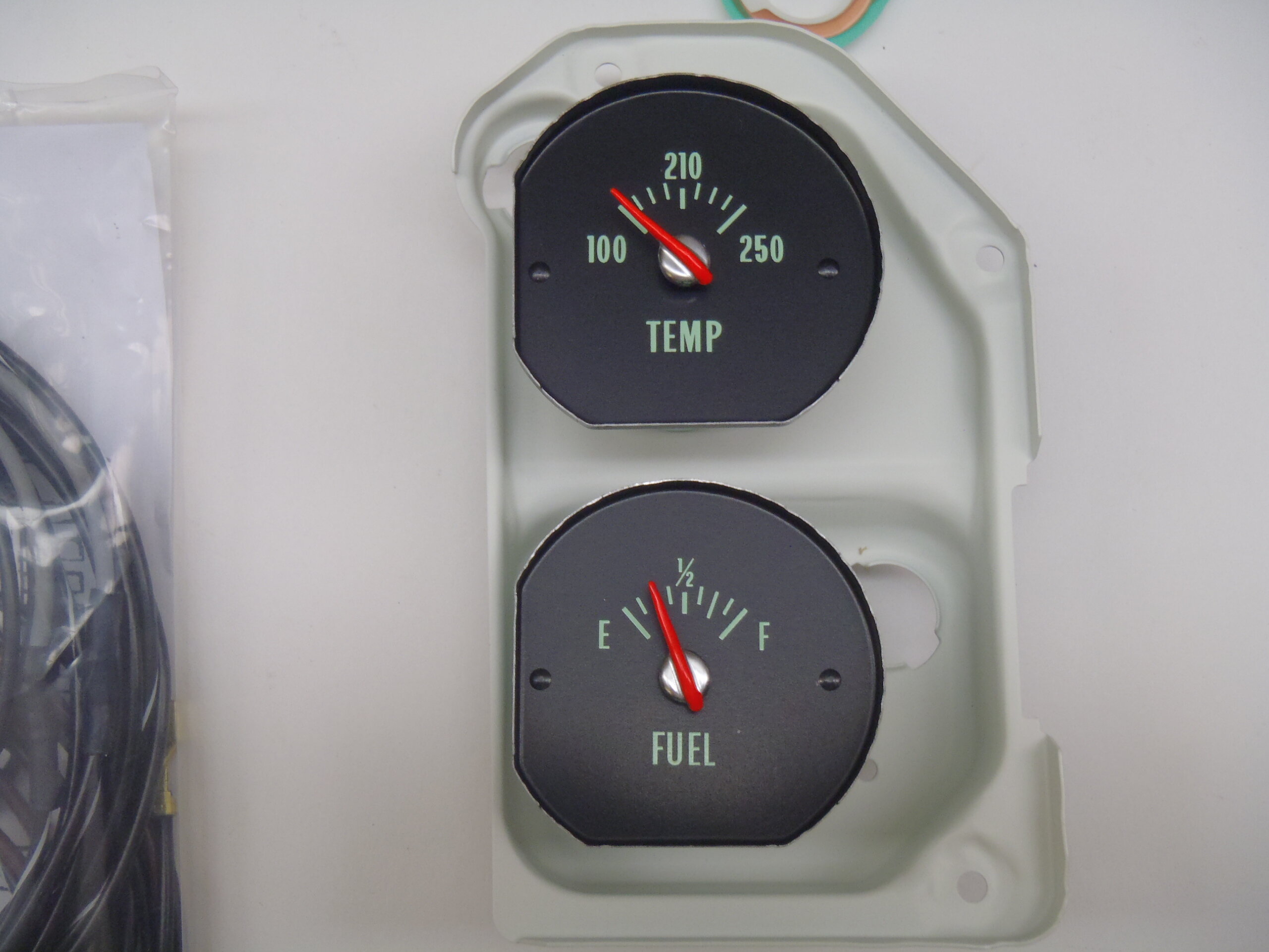
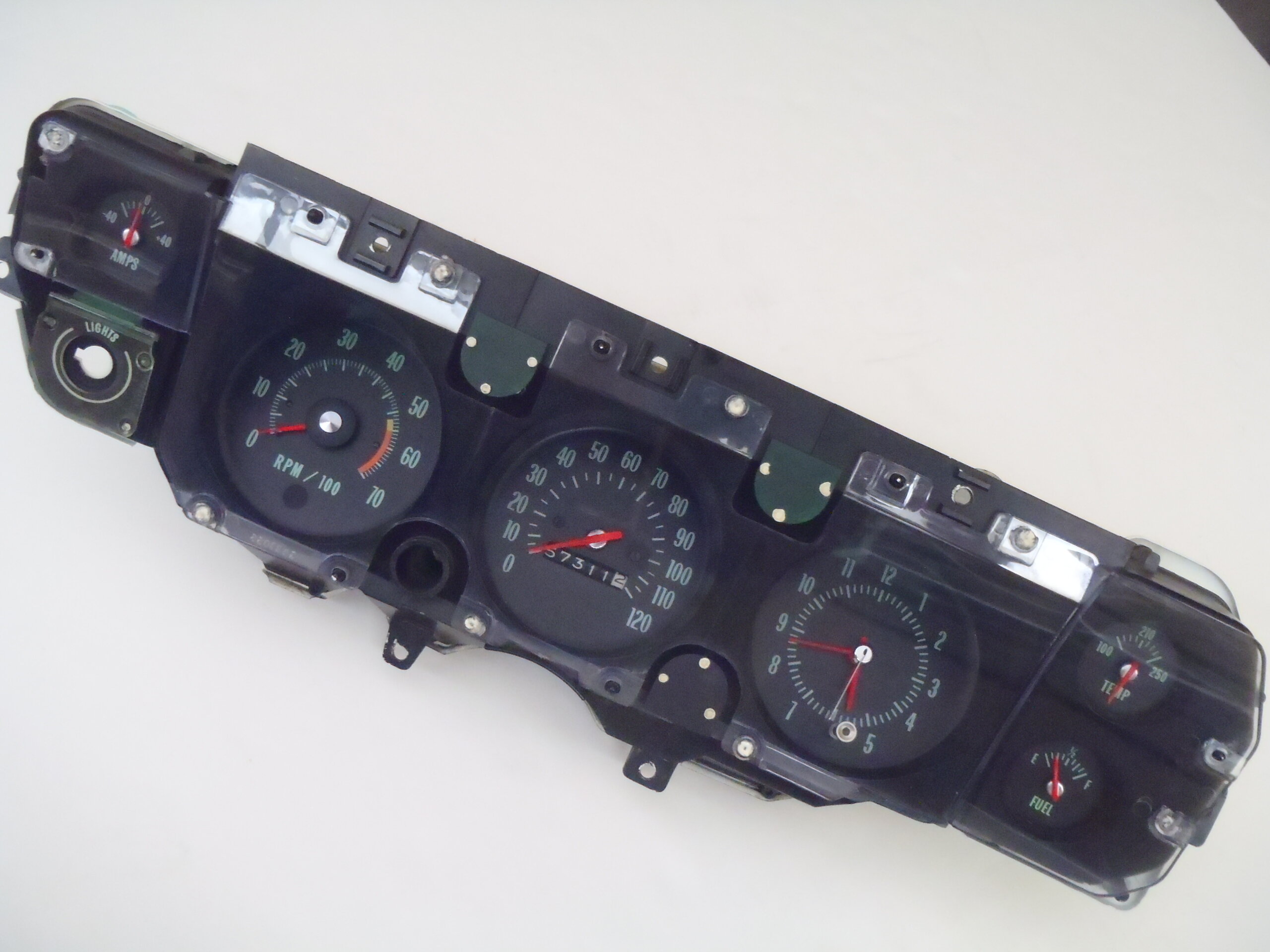
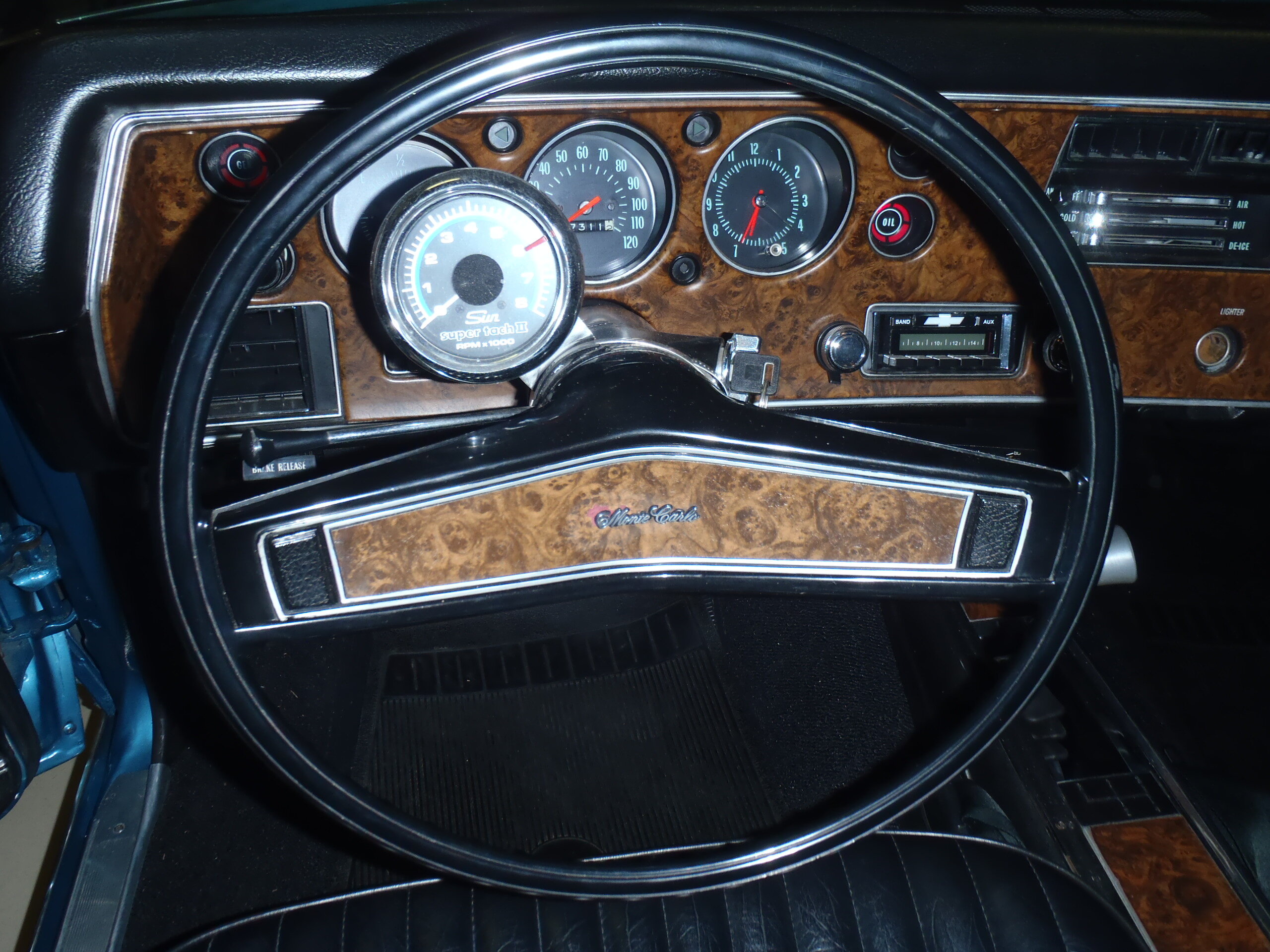
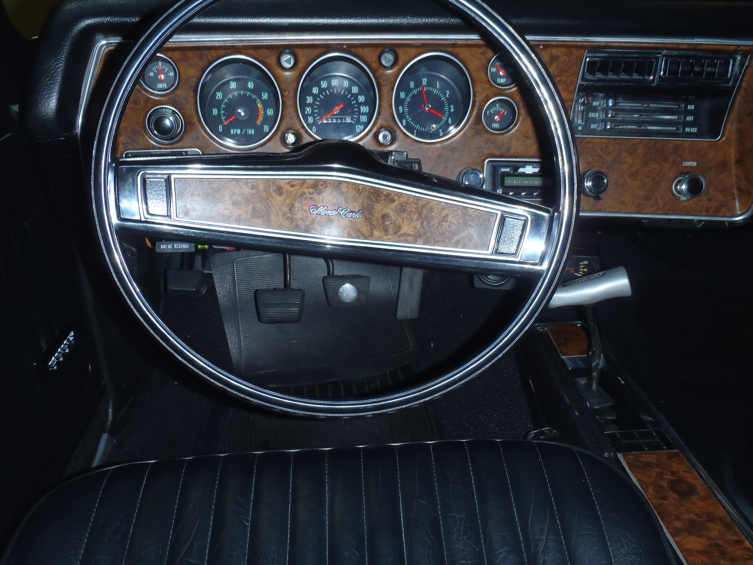
Several members, including myself, have successfully converted to full gauge dash clusters using a kit originally supplied by sonnie24 on eBay for around $355. Before and after photos are shown below. Note: Be sure to order the kit specifically made for the '70 Chevelle/Monte Carlo because the numerals are light fluorescent green (numerals are white on the '71 & '72 kits). Here's the eBay address: https://www.ebay.com/itm/374809845164?hash=item5744685dac:g:kMIAAOSwrv5cj5T4 The sonnie24 kit works perfectly, although the original instructions he provided with his kit absolutely sucked. He may have started shipping better instructions recently. I worked with Darren Bull to develop a much more detailed and illustrated set of installation instructions for that conversion kit for a '70 Monte and can make them available to anyone who asks. Just let me know.


-
Jeff, I compared your proposed configuration to what I am running now and found the following: Front: A 15x7 wheel with +12 mm offset (4.5" backspace) should work fine with the 225/70-15 tire. It will be just .2" closer to your fender well on top and have .55" more inboard and outboard clearance than the 255/60-15 I am running on the same wheel specifications. Rear: A 15x8 wheel with +25mm offset (5.5" backspace) is questionable with the big 275/60-15 tire because it pushes the wheel tire assembly a full .5" further inboard than my current configuration using a 15x8 wheel with +12mm (5" backspace). Of course, that also gives you .5" more outside sidewall clearance but your wheel/tire combo will not be optimally centered. If you try it and find that your tire is too close to your frame or inside fender well, you can add a 1/2" wheel spacer to move the assembly outboard to achieve exactly what a 5" backspace wheel would give you. That assumes your current wheel studs are long enough or can be replaced with longer ones. A 15x8 rim with 0 offset (4.5" backspace) will push the assembly a full half inch further outboard (than my current configuration) resulting in very little (approx 1/4") sidewall clearance with an untrimmed wheel well lip. That would not be an optimal centering of the wheel/tire assembly either. If 15x7 +12mm offset and 15x8 +25mm offset are the only/best choices offered in the wheels you want, it might be worth taking a chance, but be prepared to use a wheel space on the rear if that combo give too little inboard clearance. A 275/60 is a pretty wide tire so positioning it correctly is important. BTW, most wheel manufacturers spec their wheels in mm of offset because that measurement is relative to the center of the rim regardless of width while the backspace measurement is relative to the inside rim lip which varies with each different rim width. When you are talking about overall configurations that use different wheel widths it is best to focus on offset specs rather than backspace. If your wheel supplier/manufacturer only communicates using the backspace spec, be sure you know which rim width you are talking about to avoid confusion. Good luck.
-
Tiresize.com says there are no tires available in 265/60-15. Many of us are running 275/60-15s on the rear with 8" wide wheels and 5" backspace (+12mm offset) so maybe that is what you are thinking. However, you will quickly get into tire rubbing on tight turns with stock suspension if you put anything larger than a 255/60-15 on the front, especially with a 5" backspace on an 8" wide rim. If you want all four wheel/tire combos to be the same, 255/60-15s on 8 inch wheels with 5" backspace may be a practical limit. If you want wider (and taller) rear tires, 275/60- 15s will work with your wheel choice.
-
At that price, I might even be able to replace the hood .... 🙃 Hope someone in the club picks it up.
-
Check this gorgeous '70 SS454 out! https://www.ebay.com/itm/175809180789?hash=item28ef0b3475:g:0igAAOSwPT1kqhO9&amdata=enc%3AAQAIAAAA4I4KYRZCJlkcp17NB46zuOKOZWSr7b%2B%2BhrkJnkTp5NTgXN%2BezlxhxIQGpXWEuvLzD9uTAUsNjx80LM7R4xOAReSbhlb5y9b8FUjCAltBoQ98fU0yF%2FT7u%2FcRWSJf%2FvN1tJ4WGgWDZJwuImL30oEN0HfVd31x3dkA4CN4cEykdN5PmgiWk7kTRAcPtjjB%2FaZP76xWAqio1TBjS3%2BuKCOA5dM0z2mLGj84%2F2ZcQkEop4T48NdSjAEYaBCc13yaZyYx3zFZLJcsY%2Bqtj7WnCKVbaMowPPPPgcEckikqKAs4nLuL|tkp%3ABk9SR9qAhKSnYg